Distributed fiber sensing technical scheme and system for monitoring of concrete panel dam seepage

A technology of distributed optical fiber and sensing technology, applied in the field of distributed optical fiber sensing technology type and system, can solve the problems of not being reasonably reliable, the optical demodulator is not fully applicable, and the electric heat energy is small, and achieves on-site laying protection. Large workload, guaranteed on-site protection and survival rate, and sufficient heating energy

Inactive Publication Date: 2016-05-25
SICHUAN UNIV
View PDF9 Cites 11 Cited by
  • Summary
  • Abstract
  • Description
  • Claims
  • Application Information

AI Technical Summary

Problems solved by technology

In short, the problems are: 1) The electric heating energy is relatively small, and the temperature rise without leakage is only on the order of 2~5°C; 2) The optical demodulator for Raman fiber optic sensing is not completely suitable for

Method used


Image

  • Distributed fiber sensing technical scheme and system for monitoring of concrete panel dam seepage
  • Distributed fiber sensing technical scheme and system for monitoring of concrete panel dam seepage
  • Distributed fiber sensing technical scheme and system for monitoring of concrete panel dam seepage

Examples


Embodiment Construction

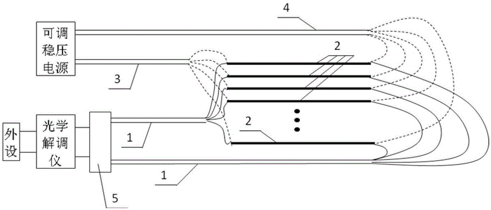
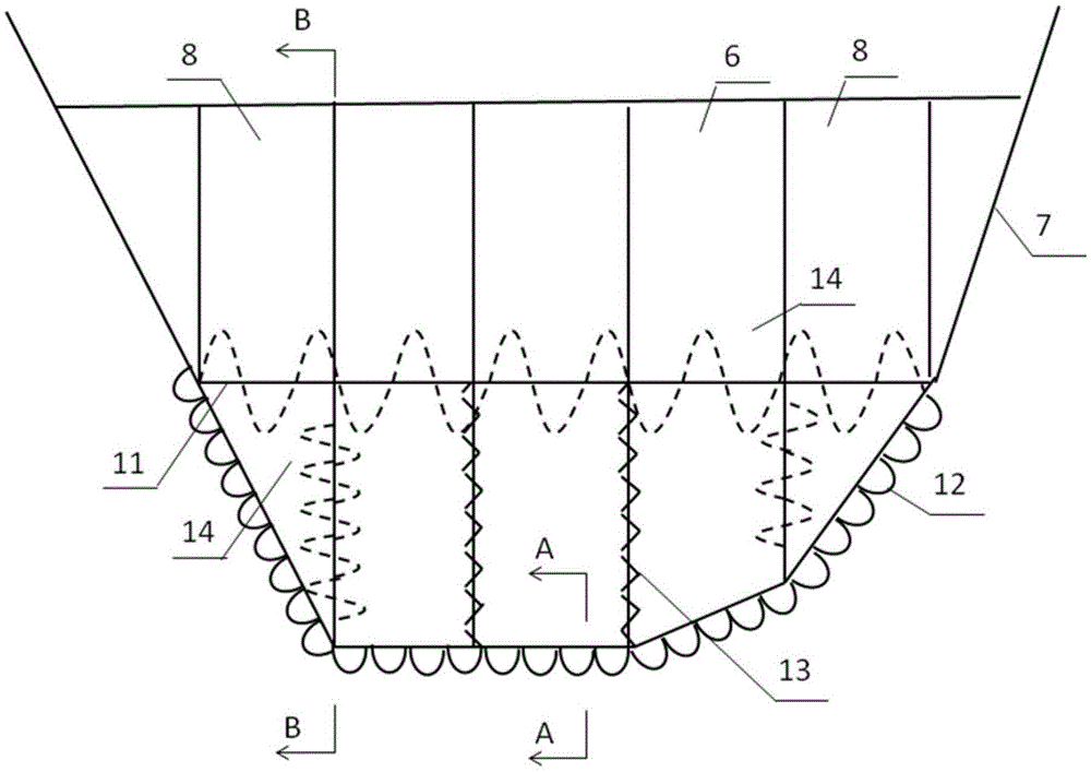
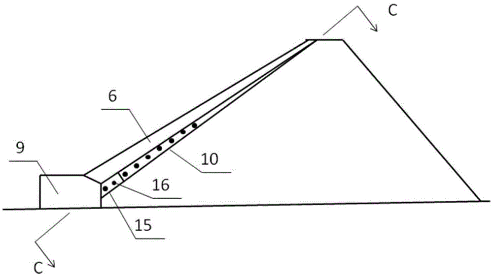
[0042] (1) In the asphalt (cement) mortar cushion layer laid under the peripheral seam-vertical seam of the panel, a groove for laying photoelectric composite cables is reserved along the lower opening of the seam surface, about 15~25cm wide and 8~15cm deep, and optical cables are laid at the bottom of the groove (The distance between the two optical cables is about 1~3cm). After the optical cable is laid, installed and positioned and inspected by OTDR, the laying groove is filled with gravel material and manually compacted and leveled. Construction details: The PVC gasket laid on the top surface of the mortar cushion can extend to the bottom surface of the embedding groove, but do not cover the optical cable or fill the gravel material; when the laying groove is adjacent to the subsequent concrete pouring operation, do not let the concrete material or cement slurry into the laying groove, to avoid covering / pollution of optical cables and gravel filling materials.

[0043] Si...


PUM


Abstract

The invention discloses a distributed fiber sensing technical scheme and system for monitoring of concrete panel dam seepage. The distributed fiber sensing technical scheme for monitoring of concrete panel dam seepage is characterized in that a strengthened heated photoelectric composite cable is used so that the fiber temperature rise of a non- seepage part achieves 15-30DEG C; a temperature anomaly signal because of great strengthened seepage is generated; and by means of coordination with a high precision Brillouin optical time domain analyzer PPP-BOTDA/Brillouin-Rayleigh synthetic system TW-COTDR or a Raman DTS optical interrogator, the signal to noise ratio is greater than 10, so that the temperature rise signal for avoiding that water leakage is submerged by the background noise/observation error and the height reliability for seepage diagnosis can be guaranteed. For the distributed fiber sensing technical scheme and system for monitoring of concrete panel dam seepage, as the implementation mode of the technical scheme is provided, and especially, the fiber arranging-laying mode aiming at the respective feature of a seam and a damaged area of the panel is provided, a large scope of coverage and on-line remote detection for the potential risk parts of the surrounding seams, the vertical seams and water leakage of the panel can be realized, and also occurrence of reliable observation and seepage identification, distributed parts and approximate quantitative estimation of the seepage intensity and evolution and development tendency can be realized.

Description

technical field [0001] The invention relates to a distributed optical fiber sensing technology type and system for monitoring the leakage of the peripheral seam-vertical seam of a concrete face rockfill dam and the face damage area, which can realize large-scale real-time online remote measurement of the seepage of a concrete face rockfill dam project. Background technique [0002] As we all know, the primary cause of failures and major accidents of concrete face rockfill dams at home and abroad is concentrated leakage. The failure of the highest face dam, that is, the face dam behind the ditch in my country, is caused by leakage. Serious water leakage accidents in face dams such as Sanbanxi and Zhushuqiao led to emptying of the reservoir for repair. Peripheral seam-vertical seam leakage and water leakage accidents in the panel damage area have strong concealment and high randomness in time and space. Conventional point-type monitoring equipment is powerless to monitor its...

Claims


Application Information

Patent Timeline
IPC IPC(8): G01M3/04
CPCG01M3/04
Inventor 孙曼刘浩吾陈江王琛唐天国
Owner SICHUAN UNIV
Why Eureka
Try Eureka