Luminescence control circuit and shift register

A light-emitting control circuit, shift register technology, applied in static memory, digital memory information, instruments, etc., can solve the problems of clock signal multiplication, signal line crosstalk, adverse effects on stability and reliability, etc., and achieve the output signal waveform. Stable, high gate reliability effect

Active Publication Date: 2016-05-25
TRULY HUIZHOU SMART DISPLAY
View PDF11 Cites 13 Cited by
  • Summary
  • Abstract
  • Description
  • Claims
  • Application Information

AI Technical Summary

Problems solved by technology

The disadvantage of this type of scheme is that the multiplication of the required clock signal has an adverse effect on stability and reliability
[0006] For example, the technical solution disclosed in the Chinese patent application with the publication number CN103886836B can directly generate the shift light emission control signal, but there is a moment when the output stage TFT is turned off at the same time (high impedance state), and the output can only be maintained by parasitic capacitance, which may cause Affected by crosstalk from other signal lines

Method used


Image

  • Luminescence control circuit and shift register
  • Luminescence control circuit and shift register
  • Luminescence control circuit and shift register

Examples


Embodiment Construction

[0039] The implementation of the present invention will be described in detail below in conjunction with the accompanying drawings. The accompanying drawings are only for reference and description, and do not constitute a limitation to the protection scope of the present invention.

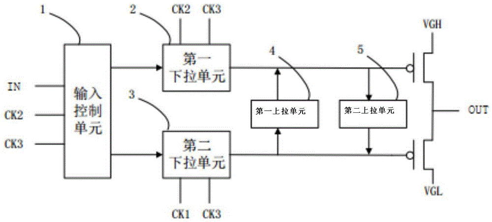
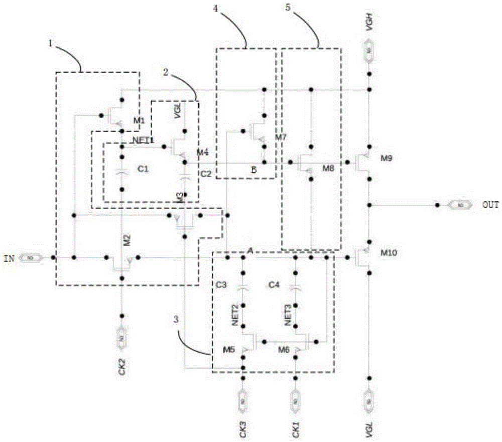
[0040] Such as figure 1 As shown, this embodiment provides a lighting control circuit as a shift register unit circuit, including: a first clock signal input terminal CK1, a second clock signal input terminal CK2, a third clock signal input terminal CK3, a signal input terminal IN , the luminescence control signal output terminal OUT, the constant high-level voltage signal terminal VGH and the constant low-level voltage signal terminal VGL, and the input control unit 1 is connected between the signal input terminal IN and the luminescence control signal output terminal OUT. The pull-up unit 2 and the second pull-down unit 3, the first pull-up unit 4 and the second pull-up unit 5;

[0041] In this...


PUM


Abstract

The invention provides a luminescence control circuit which is taken as a shift register unit circuit. The circuit comprises a first clock signal input end, a second clock signal input end, a third clock signal input end, a signal input end, a luminescence control signal output end, a constant high level voltage signal end and a constant low level voltage signal end, wherein an input control unit, a first pull-down unit, a second pull-down unit, a first pull-up unit and a second pull-up unit are connected between the signal input end and the luminescence control signal output end. The invention further provides a shift register, grid control nodes of ninth and tenth film transistors of an output level TFT have stable and controllable work voltages at each work stage, the ninth and tenth film transistors realize conduction by turns, and the simultaneous turn-off situation does not occur. According to the circuit, circuit output signal waveforms are stable, grid reliability is high, after simulation verification, output signal waveforms of each level of cascade circuits are stable.

Description

technical field [0001] The present invention relates to the field of flat panel display technology, in particular to a light emitting control circuit and a shift register for array substrate driving. Background technique [0002] Active Matrix Organic Light Emitting Diode (Active Matrix Organic Light Emitting Diode, referred to as: AMOLED) is a flat panel display technology that develops rapidly in recent years. Due to the large current required to drive organic light-emitting diodes (OLEDs), amorphous silicon (a-Si) technology is difficult to meet the demand due to the influence of electron mobility; the electron mobility of low-temperature polysilicon (LTPS) technology can reach 300cm 2 / V·s, suitable for small and medium-sized AMOLEDs. [0003] Due to technical or technical reasons, the pixel driving circuit needs to realize the threshold voltage compensation function through the pixel compensation circuit. In order to achieve a better display effect, the pixel compensa...

Claims


Application Information

Patent Timeline
Patent Type & Authority Applications(China)
IPC IPC(8): G09G3/3258G11C19/28
CPCG09G3/3258G11C19/28
Inventor 阮伟文吴锦坤胡君文田栋协谢志生苏君海李建华
Owner TRULY HUIZHOU SMART DISPLAY
Why Eureka
Try Eureka