Ultrasonic reinforced micro-channel heat exchanger

An ultrasonic and micro-channel technology, which is applied in electric solid devices, semiconductor devices, semiconductor/solid-state device components, etc., can solve the problem of inability to apply microelectronic heat dissipation, large volume of shell-and-tube heat exchangers, and relatively high cooling fluid requirements. It can reduce the kinematic viscosity coefficient, enhance the operation reliability, and enhance the heat transfer effect.

Inactive Publication Date:
View PDF9 Cites 9 Cited by
  • Summary
  • Abstract
  • Description
  • Claims
  • Application Information

AI Technical Summary

Problems solved by technology

[0004] The Chinese patent "Ultrasonic Scale Prevention and Descaling Enhanced Heat Exchange Shell-and-Tube Heat Exchanger" (application number: CN201220480982.5) discloses a high-efficiency shell-and-tube heat exchange equipment, which is characterized by the use of ultrasonic The cavitation mechanism cleans the dirt settled in the heat exchanger, reduces the heat transfer resistance and improves the heat transfer effect; Regular blowdown is required in
However, the above patents on microchannels improve the heat transfer effect to a certain extent by improving the conventional microchannel heat exchanger, but the flow resistance of the fluid in the microchannel is relatively large, and only by changing the arrangement of the pin fins and the shape can not be completely solved; at the same time, the requirements for the cooling fluid are high, and it will generate dirt, increase the thermal resistance, and deteriorate the heat transfer effect

Method used


Image

  • Ultrasonic reinforced micro-channel heat exchanger
  • Ultrasonic reinforced micro-channel heat exchanger
  • Ultrasonic reinforced micro-channel heat exchanger

Examples


Embodiment Construction

[0024] The present invention will be further described below in conjunction with the accompanying drawings and embodiments.

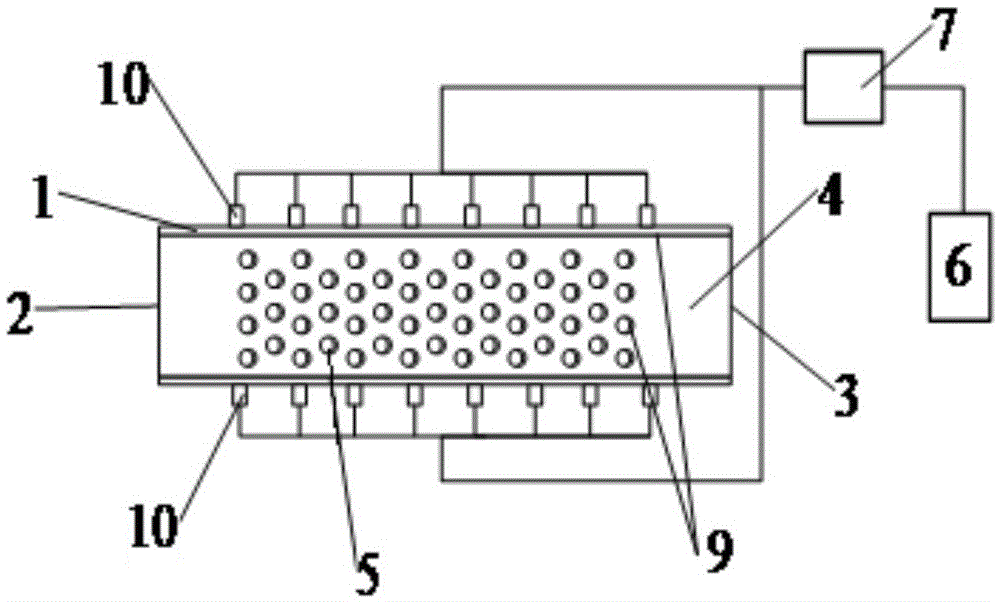
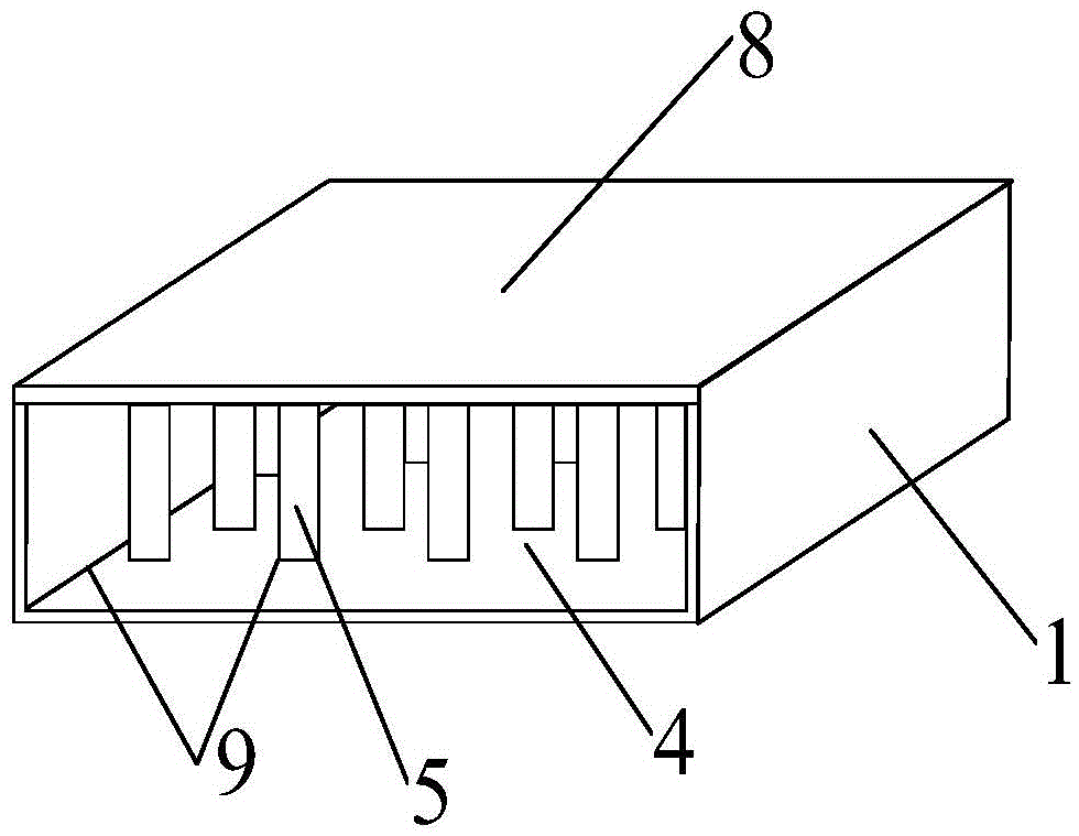
[0025] like figure 1 As shown, the ultrasonically enhanced micro-channel heat exchanger of this embodiment includes a heat dissipation shell, a water cooling system, a microneedle rib 5, an ultrasonic generator 6, an ultrasonic transducer 7 and an ultrasonic transducer vibrator 10;

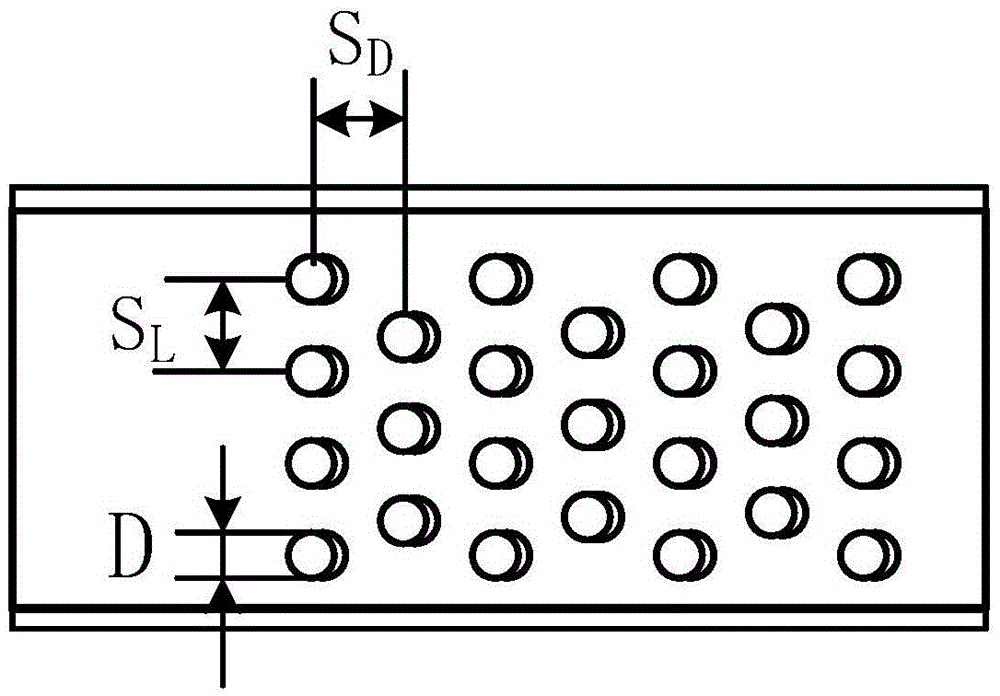
[0026] Wherein, the water cooling system includes a cooling water channel 4, a water inlet 2 and a water outlet 3, the cooling water channel 4 is arranged inside the heat dissipation housing, and the cross section of the cooling water channel 4 is rectangular (see for details figure 2 ), the water inlet 2 and the water outlet 3 are respectively arranged on the heat dissipation housing, and the water inlet 2 and the water outlet 3 are respectively connected with the cooling channel 4 to form a water cooling system; the cooling medium can be deionized water or ethanol, which...


PUM


Abstract

The invention provides an ultrasonic reinforced micro-channel heat exchanger. The heat exchanger comprises a shell, a water-cooling system, micro pin fins, an ultrasonic generator and an ultrasonic transducer, wherein the water-cooling system comprises a cooling water channel, a water inlet and a water outlet; the cooling water channel is arranged in the shell; the water inlet and the water outlet are connected with the cooling water channel to form the water-cooling system; the shell comprises a channel main body and an upper sealing cover; the channel main body and the upper sealing cover are connected in a sealing manner; the micro pin fins and the cooling water channel are arranged in the channel main body; the micro pin fins are arranged along the axial direction of the channel main body; the cooling water channel is formed in the spaces among the micro pin fins, and the spaces between the micro pin fins and the inner wall of the channel main body; ultrasonic transducer oscillators are distributed on the two sides of the channel main body; and the ultrasonic generator is connected with the transducer through a wire. According to the ultrasonic reinforced micro-channel heat exchanger, the ultrasonic generator is adopted to give out high-frequency signals to enable the transducer to generate ultrasonic vibration; an ultrasonic cavitation effect generated by the cooling water is changed into an ultra-turbulent flow state, so that the cooling effect is reinforced; and in addition, dirt in the channel can be cleaned at any time, and the heat transfer resistance is lowered.

Description

technical field [0001] The invention relates to a micro-channel heat exchanger applied to heat dissipation of microelectronics, in particular to a technology for strengthening micro-channel heat exchange, anti-scaling and descaling by using an ultrasonic cavitation mechanism. Background technique [0002] The field of microelectronics is the first engineering field to propose micro-scale flow and heat transfer problems. With the rapid development of electronic computer capacity and speed and the requirements of missiles, satellites and military radars for high-performance modules and high-power devices, on the one hand, the characteristics of devices The smaller the size, the better, and it has developed from micron to submicron. On the other hand, since 1959, the integration level of devices has been increasing at a high rate of 40% to 50% every year. With the improvement of integration, the increase rate of component heat flux will be even more alarming. The resulting exce...

Claims


Application Information

Patent Timeline
Patent Type & Authority Applications(China)
IPC IPC(8): H01L23/367H01L23/473
CPCH01L23/367H01L23/473
Inventor 李栋张文娣赵孝保朱琳钱晨露
Why Eureka
Try Eureka