Online detecting and eliminating device and method for melt channel material defects in laser metal forming

A metal forming and detection device technology, which is applied in the direction of measuring devices, optical testing flaws/defects, and analyzing materials, can solve the problems of targeted elimination, inability to scan online detection of small material defects, melt channel forming, etc., and achieve easy realization and elimination Effect of internal material defects, reducing the risk of fatigue fracture

Inactive Publication Date: 2016-06-01
XIAN UNIV OF TECH +2
View PDF7 Cites 21 Cited by
  • Summary
  • Abstract
  • Description
  • Claims
  • Application Information

AI Technical Summary

Problems solved by technology

[0004] Another object of the present invention is to provide an online detection and elimination method for the material defects of the molten channel in laser metal forming by using the above-mentioned device, without suspending the forming product

Method used


Image

  • Online detecting and eliminating device and method for melt channel material defects in laser metal forming
  • Online detecting and eliminating device and method for melt channel material defects in laser metal forming
  • Online detecting and eliminating device and method for melt channel material defects in laser metal forming

Examples


Embodiment

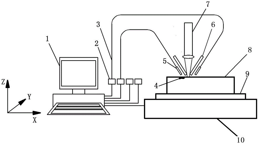
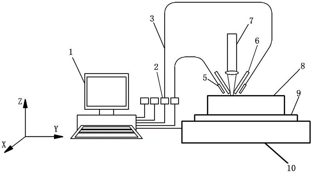
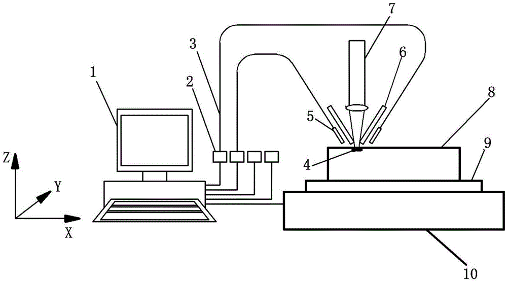
[0036] A TA15 titanium alloy cuboid part with a length, width and height of 150×50×60 mm is fabricated by laser deposition forming, and the titanium alloy part 8 is located above the substrate 9 and the workbench 10 . The (x, y) coordinate orientation of the lower left corner of part 8 in the forming plane is (0mm, 0mm). The forming process parameters adopted are: laser power 300W, scanning speed V 10mm / s, powder feeding rate 4.9g / min, laser spot diameter d 0.5mm, layer thickness 0.1mm, overlapping rate 40%, scanning method For reciprocating scanning. When making the part, the device and method of the present invention are used to realize the online detection and elimination of material defects of the melting channel in laser deposition forming.

[0037] The fiber-optic two-color thermometer 2 used in this example has a response time of 2ms, the temperature probe 5 can withstand a high temperature of 250°C, the temperature measurement range is 350-1300°C, the temperature meas...


PUM


Abstract

The invention discloses an online detecting and eliminating device and method for melt channel material defects in laser metal forming. The device and method are suitable for a laser metal deposition forming process. The device comprises four optical fiber type double-color temperature gauges, and four temperature measuring probes of the optical fiber type double-color temperature gauges are fixed to the left side, the right side, the front side and the back side of a coaxial powder feeding nozzle of a forming system correspondingly; detection aiming points of the four temperature measuring probes are aligned with the left side, the right side, the front side and the back side of a forming scanning laser spot on a forming plane correspondingly, the detection aiming points are away from the center of the laser spot by a certain micro-distance, and the four temperature measuring probes, the coaxial powder feeding nozzle and a laser beam move together; during forming, when the coaxial powder feeding nozzle and the laser beam conduct forming scanning in any one of the -X direction, the X direction, the -Y direction and the Y direction, the temperature measuring probe located at the side opposite to the scanning direction of the coaxial powder feeding nozzle is used for detecting the temperature of the position, away from the laser spot by a certain micro-distance, of a high-temperature melt channel, and when the temperature mutates abnormally, it is judged that the material defects exist in the position, the defect positions are determined, and laser targeted remelting is carried out on the defects.

Description

technical field [0001] The invention belongs to the technical field of laser metal additive manufacturing, and in particular relates to an online detection device for material defects of a melting channel in laser metal forming, and also relates to a method for using the device to realize online detection and elimination of material defects in a melting channel in laser metal forming. And the method is applicable to the laser metal deposition shaping process. Background technique [0002] Laser Metal Deposition Forming (Laser Metal Deposition Forming, LMDF) is commonly known as laser metal 3D printing. This technology can realize the direct near-net shape of complex metal parts by means of layer-by-layer laser melting deposition of metal materials according to the computer three-dimensional model without any mold and tooling, and has the advantages of short manufacturing cycle and small processing allowance. The unique advantages of high material utilization rate and high p...

Claims


Application Information

Patent Timeline
IPC IPC(8): B22F3/00G01N21/95G01K11/32B33Y10/00B33Y30/00B33Y50/02
CPCG01K11/32G01N21/95B22F3/00B33Y10/00B33Y30/00B33Y50/02G01N2201/08
Inventor 解瑞东李涤尘张安峰
Owner XIAN UNIV OF TECH
Why Eureka
Try Eureka