Automatic welding gun for realizing arc stud welding of T-shaped welding stud

A technology of automatic welding and stud welding, which is applied in the direction of arc welding equipment, electrode characteristics, welding equipment, etc., can solve problems such as unsuitable use requirements, reduced welding efficiency, and shortened welding arc ignition distance, so as to meet the requirements of use and The effect of maintenance, avoiding short service life and prolonging service life

Active Publication Date: 2016-06-01
胡长建
View PDF5 Cites 19 Cited by
  • Summary
  • Abstract
  • Description
  • Claims
  • Application Information

AI Technical Summary

Problems solved by technology

The above-mentioned driving structure has the following main disadvantages: (1) In actual use, due to the existence of factors such as machining errors, installation errors, and thermal deformation of the welding torch shell, the concentricity between the shaft sleeve and the fixed sleeve will not be high, so that the The main shaft body and the moving iron core, which are fixedly connected at the head and tail, increase the resistance when moving axially, which greatly increases the wear between the main shaft body and the shaft sleeve, as well as between the moving iron core and the fixed sleeve, making the service life of the welding torch very short. It can only be used for half a year, and it can be used for one year at most; (2) It is easy to cause the moving iron core to be stuck in the fixed sleeve or the moving iron core cannot be inserted into the fixed sleeve, so that the axial

Method used


Image

  • Automatic welding gun for realizing arc stud welding of T-shaped welding stud
  • Automatic welding gun for realizing arc stud welding of T-shaped welding stud
  • Automatic welding gun for realizing arc stud welding of T-shaped welding stud

Examples


Embodiment

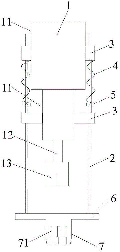
[0028] Such as figure 1 Shown: this embodiment provides an automatic welding gun for realizing arc stud welding of T-shaped welding nails, including a welding torch main body 1, the welding torch main body 1 including a housing 11, a main shaft 12 and a utility model arranged at the front end of the main shaft 12 To install the welding nail chuck 13; on both sides of the housing 11 is provided with guide posts 2, on each side of the housing 11 is provided with a guide sleeve 3, each side of the guide post 2 It is located in the upper and lower guide sleeves 3 on the same side, and a spring 4 is sleeved on the guide post 2 between the upper and lower guide sleeves 3, and a limit block 5 is provided at the lower end of the spring 4 (adjustable Nuts, convenient for adjustment and operation), a fixing seat 6 is fixedly connected to the lower ends of the guide posts 2 on both sides, and a perforation is provided on the fixing seat 6 and directly under the welding nail chuck 13 for th...


PUM


Abstract

The invention discloses an automatic welding gun for realizing arc stud welding of a T-shaped welding stud. The automatic welding gun comprise a welding gun main body; the welding gun main body comprises a shell, a main shaft body, a welding stud clamping head, and a driving mechanism which is used for driving the main shaft body to perform lifting motion; guide columns are arranged at the two sides of the shell; guide sleeves are respectively arranged at the upper and lower parts of the shell at each side; the guide column at each side penetrates into the upper and lower guide sleeves at the same side; a spring sleeves the guide column positioned between the upper and lower guide sleeves; a limiting block is arranged at the lower end of the spring; the lower ends of the guide columns at the two sides are fixedly connected with a fixing seat; a passing hole for the welding stud clamping head to smoothly pass through is formed on the fixing seat and under the welding stud clamping head; a ceramic ring clamping head, under the passing hole, is fixedly connected with the bottom of the fixing seat. The welding gun disclosed by the invention is capable of realizing automatic clamping and separation of the T-shaped welding stud and a ceramic ring for the first time, can be matched with a robot or a three-axis motion platform in use, and is capable of realizing automatic arc stud welding of the T-shaped welding stud.

Description

Technical field [0001] The invention relates to an automatic welding gun used for arc stud welding, in particular to an automatic welding gun for realizing T-shaped welding nail arc stud welding, and belongs to the technical field of stud welding equipment. Background technique [0002] Arc stud welding uses the welding arc as the heat source, the ceramic ring as the protective measure, and the stud itself as the electrode. Through the welding arc, the stud and the weldment (plate or pipe) are stably burned, and the weldment is welded. The zone is heated to form a molten pool. After the end of the stud forms a molten layer, the stud is inserted into the molten pool at high speed under the action of mechanical pressure such as a welding gun, and the liquid metal is squeezed into the forming groove of the porcelain ring, thereby forming a high-speed joint The planting welding method is widely used in the planting of medium and thick plates in the construction of large structures su...

Claims


Application Information

Patent Timeline
IPC IPC(8): B23K9/28B23K9/20
CPCB23K9/20B23K9/28
Inventor 胡长建邓显红
Owner 胡长建
Why Eureka
Try Eureka