Device for regulating and controlling actual supply amount of urea entering exhaust system and regulating and controlling method

An exhaust system and control device technology, which is applied to the electronic control of exhaust treatment devices, exhaust devices, exhaust treatment and other directions, can solve the difficulties in realization and popularization, the high cost of emission standard process, and the inability to meet the requirements of excessive urea injection. And other issues

Inactive Publication Date: 2016-06-01
金有纯
View PDF5 Cites 8 Cited by
  • Summary
  • Abstract
  • Description
  • Claims
  • Application Information

AI Technical Summary

Problems solved by technology

However, since there are many factors that affect the actual supply of urea, it is difficult to maintain a perfect balance between the amount of urea output from the urea tank and the amount of urea injected into the exhaust system, so even the best injection strategy is difficult to solve the maximum ammonia leakage problem, but only solves the problem of average ammonia leakage
In order to meet the standard’s requirements for NOx emissions and ammonia leakage at the same time, in the prior art, the SCR catalyst is increased, or EGR is used to reduce NOx first and then SCR is used, that is, EGR and SCR are cascaded, and other alternative methods, but the cost is too high. It is quite difficult to realize and popularize the high emission standards of the Euro VI standard
[0006] The invention overcomes the defects in the prior art that urea injection is difficult to control, excessive urea injection cannot meet the emission standards, and the process cost is too high, and proposes a device and a method for regulating the actual supply of urea entering the exhaust system

Method used


Image

  • Device for regulating and controlling actual supply amount of urea entering exhaust system and regulating and controlling method
  • Device for regulating and controlling actual supply amount of urea entering exhaust system and regulating and controlling method
  • Device for regulating and controlling actual supply amount of urea entering exhaust system and regulating and controlling method

Examples


Embodiment 1

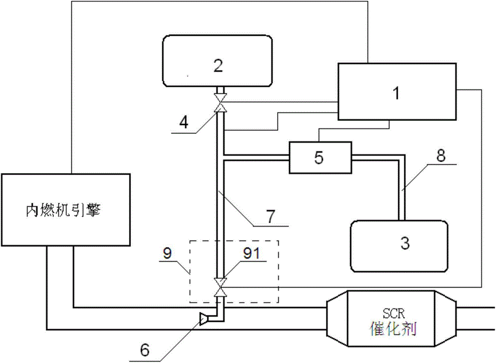
[0049] image 3 Shown is a structural diagram of the device for regulating the actual supply of urea entering the exhaust system in this embodiment. Wherein, the urea control device 9 includes a control gas valve 91 . The control air valve 91 is arranged on the main pipeline 7 and is located between the urea pipeline 8 and the nozzle device 6 . The control air valve 91 is controlled by the electronic control unit 1 , and by adjusting the opening and closing state of the control air valve 91 , the gating and closing between the main pipeline 7 and the nozzle device 6 are adjusted. When gated, compressed air is mixed with urea and fed into the nozzle assembly 6 to be sprayed into the exhaust system, while when closed, compressed air is mixed with urea in the main pipe 7 but cannot be fed into the nozzle assembly 6, thereby preventing excess urea Spray into the exhaust system.

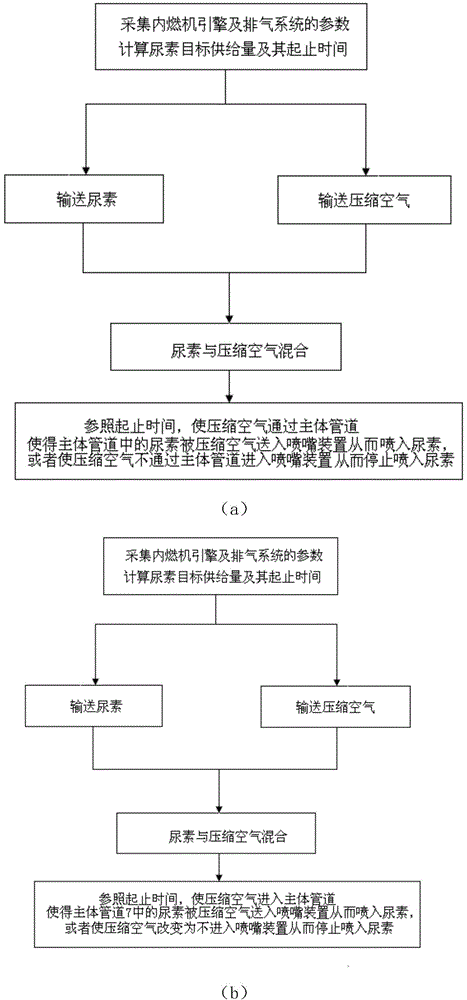
[0050] Combine the following Figure 4 The waveforms of are detailing the working flow of the devi...

Embodiment 2

[0056] Figure 5 Shown is a structural diagram of the device for regulating the actual supply of urea entering the exhaust system in this embodiment. Wherein, the urea control device 9 includes a bypass channel 92 and a bypass control gas valve 93 . The bypass channel 92 communicates with the main pipeline 7, and the communication port is located between the urea pipeline 8 and the nozzle device 6; the bypass control air valve 93 is arranged on the bypass channel 92, and the bypass control air valve 93 communicates with the electronic control unit 1, The electronic control unit 1 can regulate the opening and closing of the bypass control air valve 93 . When the bypass control air valve 93 is closed, urea and compressed air are mixed in the main pipe 7 and sprayed into the exhaust system through the nozzle device 6 . While the bypass control air valve 93 is in the open state, since the air pressure of the bypass channel 92 is lower than the exhaust back pressure of the nozzle...

Embodiment 3

[0064] Figure 8 Shown is a structural diagram of the device for regulating the actual supply of urea entering the exhaust system in this embodiment. Wherein, the urea control device 9 includes a control gas valve 91 , a bypass channel 92 and a bypass control gas valve 93 . The control air valve 91 is arranged on the main pipeline 7 and is located between the urea pipeline 8 and the nozzle device 6 . The bypass channel 92 communicates with the main pipeline 7 , and the communication port is located between the urea pipeline 8 and the nozzle device 6 ; the bypass control air valve 93 is arranged on the bypass channel 92 . The control air valve 91 and the bypass control air valve 93 communicate with the electronic control unit 1 respectively, and the electronic control unit 1 can control the opening and closing of the control air valve 91 and the bypass control air valve 93 .

[0065] Combine the following Figure 9 The waveforms of are detailing the working flow of the devic...


PUM


Abstract

The invention discloses a device for regulating and controlling the actual supply amount of urea entering an exhaust system. The device comprises an electronic control unit, a compressed air source device, a urea storing device, a compressed air controlling device, a metering pump / valve, a spray nozzle device, a main pipeline and a urea pipeline and further comprises a urea regulating and controlling device. The urea regulating and controlling device is in communication with the electronic control unit; and the actual supply amount of urea actually sprayed into the exhaust system from the spray nozzle device is controlled according to starting time and ending time. The device effectively avoids the situation that urea sprayed into the exhaust system is excessive, and by means of low-cost improvement, an original exhaust system accords with a higher emission standard. The invention further discloses a regulating and controlling method for regulating and controlling the actual supply amount of the urea entering the exhaust system.

Description

technical field [0001] The invention belongs to the technical field of internal combustion engine control systems, and in particular relates to a device and a control method for regulating the actual supply of urea entering an exhaust system. Background technique [0002] There are two types of internal combustion engines, gasoline engines and diesel engines. Their working mechanisms are different, and each has its own advantages: the gasoline engine is lightweight, with small vibration and good smoothness; the diesel engine has high efficiency, and its fuel consumption is more than 30% lower than that of the gasoline engine, with large torque and high power at low speed. Generally speaking, diesel engines have many advantages and disadvantages, and the development prospects are promising. The emission pollution of internal combustion engines is mainly divided into four categories: carbon monoxide CO, hydrocarbons HC, nitrogen oxides NOx, and particulate matter PM. Gasolin...

Claims


Application Information

Patent Timeline
Patent Type & Authority Applications(China)
IPC IPC(8): F01N9/00F01N3/28
CPCF01N3/2066F01N3/208F01N9/00F01N2610/02F01N2610/085F01N2610/1493Y02T10/12Y02T10/40F01N3/222F01N2570/14F01N2610/1406F01N2900/08
Inventor 金有纯
Owner 金有纯
Why Eureka
Try Eureka