A cryogenic vacuum pump
A low-temperature vacuum and vacuum cover technology, which is applied in the direction of pumps, pump components, variable displacement pump components, etc., can solve the problems that cannot meet the requirements, and achieve the effects of long service life, safe use and high structural strength
- Summary
- Abstract
- Description
- Claims
- Application Information
AI Technical Summary
Problems solved by technology
Method used
Image

Examples
Embodiment 1
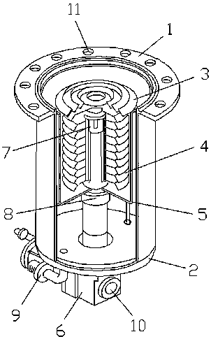
[0018] refer to figure 1 As shown, a cryogenic vacuum pump includes a flange 1, a pump body 2, a first condensing fin group 3 and a second condensing fin group 4, the flange 1 is arranged on the top of the pump body 2, and the flange 1 Welded with the pump body 2, the first condensing fin group 3 and the second condensing fin group 4 are arranged in the pump body 2, the first condensing fin group 3 is distributed horizontally, and the second condensing fin group The group 4 is vertically distributed, and a vacuum cover 5 is installed on the outside of the second condensing fin group 4, and the vacuum cover 5 is fixedly connected with the pump body 2, and the bottom of the pump body 2 is provided with a refrigerator 6, and the first A second-stage cold head 7 is installed in the middle of the condensing fin group 3, and a first-stage cold head 8 is installed below the vacuum cover 5. The second-stage cold head 7, the first-stage cold head 8, and the refrigerator 6 are sequentia...
Embodiment 2
[0026] refer to figure 1 As shown, a cryogenic vacuum pump includes a flange 1, a pump body 2, a first condensing fin group 3 and a second condensing fin group 4, the flange 1 is arranged on the top of the pump body 2, and the flange 1 Welded with the pump body 2, the first condensing fin group 3 and the second condensing fin group 4 are arranged in the pump body 2, the first condensing fin group 3 is distributed horizontally, and the second condensing fin group The group 4 is vertically distributed, and a vacuum cover 5 is installed on the outside of the second condensing fin group 4, and the vacuum cover 5 is fixedly connected with the pump body 2, and the bottom of the pump body 2 is provided with a refrigerator 6, and the first A second-stage cold head 7 is installed in the middle of the condensing fin group 3, and a first-stage cold head 8 is installed below the vacuum cover 5. The second-stage cold head 7, the first-stage cold head 8, and the refrigerator 6 are sequentia...
Embodiment 3
[0034] refer to figure 1 As shown, a cryogenic vacuum pump includes a flange 1, a pump body 2, a first condensing fin group 3 and a second condensing fin group 4, the flange 1 is arranged on the top of the pump body 2, and the flange 1 Welded with the pump body 2, the first condensing fin group 3 and the second condensing fin group 4 are arranged in the pump body 2, the first condensing fin group 3 is distributed horizontally, and the second condensing fin group The group 4 is vertically distributed, and a vacuum cover 5 is installed on the outside of the second condensing fin group 4, and the vacuum cover 5 is fixedly connected with the pump body 2, and the bottom of the pump body 2 is provided with a refrigerator 6, and the first A second-stage cold head 7 is installed in the middle of the condensing fin group 3, and a first-stage cold head 8 is installed below the vacuum cover 5. The second-stage cold head 7, the first-stage cold head 8, and the refrigerator 6 are sequentia...
PUM
 Abstract
Description
Claims
Application Information