Field suppression and over-voltage performance testing instrument applied to excitation system and testing method thereof

A technology of excitation system and tester, which is applied in the direction of motor generator testing, instrumentation, and electrical measurement, can solve the problems of hidden dangers in the safe operation of the unit, the inability to detect the performance of the demagnetization resistance, the action characteristics of the rotor overvoltage protection circuit, etc., and achieve the elimination of abnormal Effective demagnetization hidden dangers, significant economic benefits, and the effect of ensuring safe operation

Active Publication Date: 2016-06-01
NARI TECH CO LTD +1
View PDF6 Cites 7 Cited by
  • Summary
  • Abstract
  • Description
  • Claims
  • Application Information

AI Technical Summary

Problems solved by technology

Due to the lack of test equipment in most power plants, it is impossible to detect the performance of the demagnetization resistance and the action characteristics of the rotor overvoltage protection circuit, which brings hidden dangers to the long-term safe operation of the unit

Method used


Image

  • Field suppression and over-voltage performance testing instrument applied to excitation system and testing method thereof
  • Field suppression and over-voltage performance testing instrument applied to excitation system and testing method thereof
  • Field suppression and over-voltage performance testing instrument applied to excitation system and testing method thereof

Examples


Embodiment Construction

[0024] In order to make the technical means, creative features, goals and effects achieved by the present invention easy to understand, the present invention will be further described below in conjunction with specific embodiments.

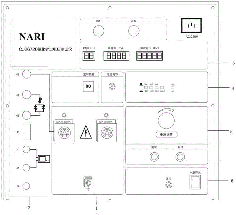
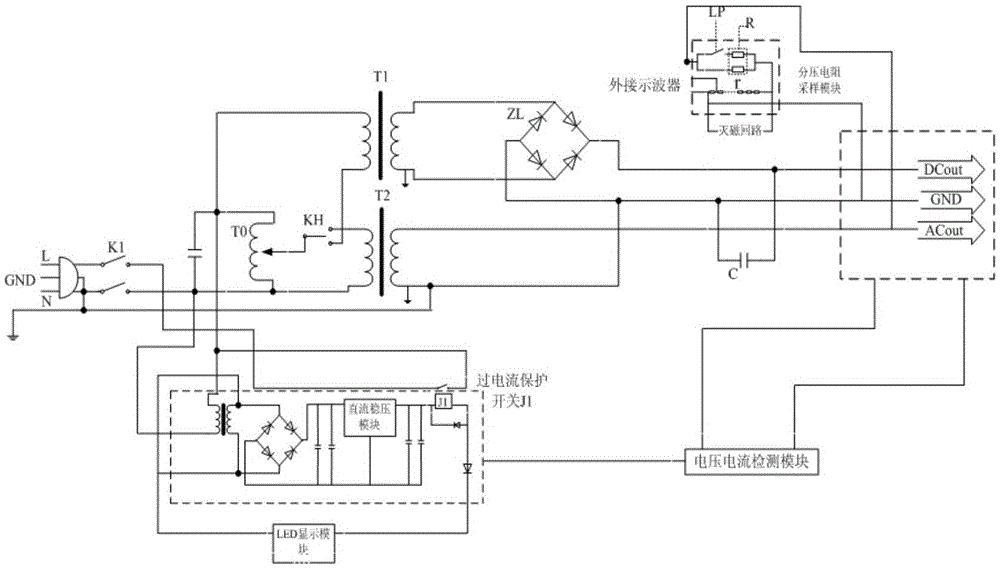
[0025] The present invention selects a voltage regulator with reasonable parameters, a step-up transformer, a rectifier filter circuit, a voltage dividing resistor sampling unit, an output voltage and loop leakage current display module, an over-leakage alarm module, and a self-protection unit, and the above-mentioned parts are integrated into the instrument box In the middle, it is equipped with an operation indicator panel, and the box has a handle and wheels, which is convenient for carrying and testing.

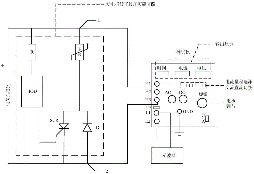
[0026] see figure 1 , Area 1 is the high-voltage AC and high-voltage DC output interface, and a step-up transformer is installed below the area; Area 2 is the external terminals L1 and L2 of the oscilloscope, the external terminals H1, H2 and...


PUM


Abstract

The invention discloses a field suppression and over-voltage performance testing instrument applied to an excitation system and a testing method thereof. The testing instrument is composed of a voltage adjusting and boosting unit, a rectifier and filter unit, a detection display unit, a function selection pressing plate, a divider resistance sampling unit, and a display unit. The voltage adjusting and boosting unit consists of a regulator, a change-over switch, a first boosting transformer, and a second boosting transformer. The detection display unit is connected with a testing loop. The function selection pressing plate can be connected to a current-limiting resistor of the testing loop selectively. The divider resistance sampling unit includes a plurality of resistors that are connected in series mutually and are connected into a high-voltage output loop. The display unit is used for displaying a testing voltage value and a testing loop leakage current. The testing instrument is connected to a single-phase power supply and then regulator carries out processing; when the first boosting transformer is collected selectively by the change-over switch, a rectifier circuit and a filter capacitor carry out processing to output a high-voltage direct current; and when the second boosting transformer is collected selectively by the change-over switch, a high-voltage alternant current is outputted and the divider resistance sampling unit is connected. According to the invention, the field suppression performance of the excitation system of the generator can be detected and the motion reliability of the electronic jumper control loop and the over-voltage protection loop can be checked.

Description

technical field [0001] The invention relates to a tester for de-excitation and overvoltage performance applied to an excitation system and a test method thereof, belonging to the technical field of generator microcomputer excitation. Background technique [0002] The function of the generator demagnetization resistor is to quickly consume the magnetic field energy stored in the generator rotor excitation winding, and quickly decay the internal potential of the generator to close to zero, especially when the generator internal or external fault occurs, it can play a role The function of protecting the generator set or reducing the loss of the generator set failure. [0003] When the generator has short circuit at the machine end, step out, loss of excitation, non-synchronous closing and other working conditions, a high overvoltage will be induced in the rotor excitation winding. If this part of the overvoltage energy cannot be absorbed in time, it will cause damage to the in...

Claims


Application Information

Patent Timeline
Patent Type & Authority Applications(China)
IPC IPC(8): G01R31/34
CPCG01R31/346
Inventor 余振许其质邵宜祥陆巍张寅葛东平
Owner NARI TECH CO LTD
Why Eureka
Try Eureka