
Built-in high-power-density permanent magnet motor integrated to 8AT transmission box

A high power density, permanent magnet motor technology, applied in the direction of magnetic circuits, electric components, electrical components, etc., can solve the problems of unable to meet the structural requirements of the gearbox, low torque density and power density, high vibration and noise of the motor, and achieve Significant magnetic concentration effect, low electromagnetic noise and high motor efficiency

Inactive Publication Date: 2016-06-01
FUJIAN YANAN ELECTRIC MACHINE
View PDF8 Cites 10 Cited by
  • Summary
  • Abstract
  • Description
  • Claims
  • Application Information

AI Technical Summary

Problems solved by technology

However, in the existing technology, the built-in permanent magnet motor has low torque density and power density, and has a large volume, which cannot meet the structural requirements of the gearbox built-in permanent magnet motor. The slot torque and tooth harmonics are large, the loss is large, and the efficiency is biased. Low, high vibration and noise of motor operation, complex structure and process, difficult to realize automatic production, high processing cost, large amount of permanent magnets, high material cost

Method used


Image

  • Built-in high-power-density permanent magnet motor integrated to 8AT transmission box
  • Built-in high-power-density permanent magnet motor integrated to 8AT transmission box
  • Built-in high-power-density permanent magnet motor integrated to 8AT transmission box

Examples


specific Embodiment approach

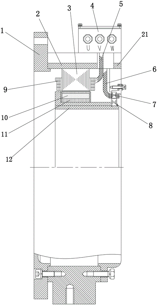
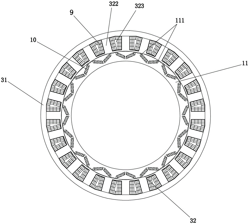
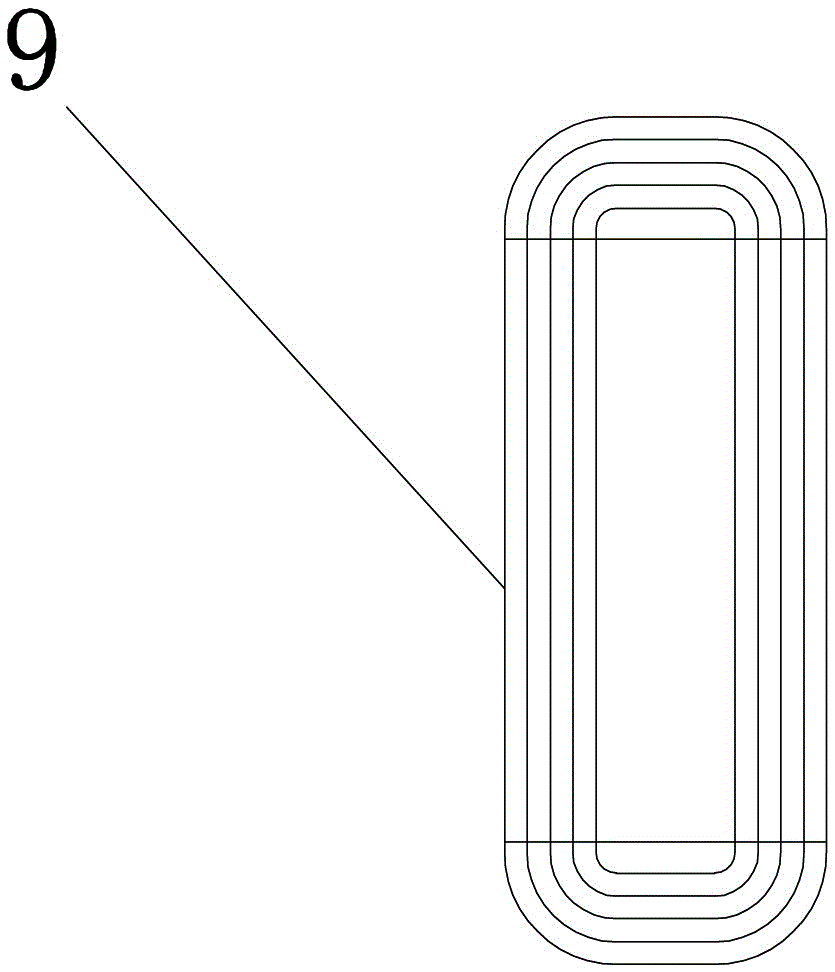
[0019] Such as Figure 1-Figure 8 As shown, a high power density permanent magnet motor integrated in an 8AT gearbox includes a gearbox flange 1, a gearbox housing 2, a built-in permanent magnet motor stator 3, a rotor 11, and a gearbox hub 12. The gearbox method The flange 1 is connected to the left end of the gearbox housing 2; the right end of the gearbox flange 1 is provided with a gearbox housing rear end cover 21; the built-in permanent magnet motor stator 3 is arranged on the inner wall of the gearbox housing 2; the built-in permanent magnet The motor stator 3 is provided with a flat wire forming winding 9; the rotor 11 is provided on the gearbox hub 12, and the rotor 11 is provided with a rotor magnet 10; the rotor 11 is located in the ring of the built-in permanent magnet motor stator 3; the flat wire forming winding 9 is connected with the outlet box 4 provided on the gearbox housing 2 through the lead-out cable 5; the gearbox hub 12 is provided with a resolver rotor...


PUM


Abstract

The invention discloses a built-in high-power-density permanent magnet motor integrated to an 8AT transmission box. The built-in high-power-density permanent magnet motor comprises a transmission box flange, a transmission box housing, a built-in permanent magnet motor stator, a rotor and a transmission box hub, wherein the transmission box flange is connected to the left end of the transmission box housing; a back end cover of the transmission box housing is arranged at the right end of the transmission box flange; the motor stator is arranged on the inner wall of the transmission box housing; a flat wire forming winding is arranged on the motor stator; the rotor is arranged on the transmission box hub; rotor magnetic steel is arranged in the rotor; the flat wire forming winding is connected with a wire outlet box; a rotary transformer rotor is arranged on the transmission box hub; a rotary transformer stator is arranged on the back end cover of the transmission box housing; the rotary transformer stator is connected with the wire outlet box; each stator punching sheet adopts a structure that a stator yoke and stator teeth are separated first and then combined; the stator punching sheet is a closed slot without teeth harmonics; and the rotor adopts a V-shaped insertion type magnetic steel structure and a cosine air gap design, so that the magnetism gathering is remarkable. The built-in high-power-density permanent magnet motor is novel in structure, can generate vibration and is small in noise, small in loss and high in efficiency.

Description

technical field [0001] The invention relates to the field of energy equipment, in particular to a high power density permanent magnet motor integrated in an 8AT gearbox. Background technique [0002] At present, the built-in permanent magnet motor has the characteristics of high torque density, high power density, high starting torque, high efficiency, and wide speed range. However, in the existing technology, the built-in permanent magnet motor has low torque density and power density, and has a large volume, which cannot meet the structural requirements of the gearbox built-in permanent magnet motor. The slot torque and tooth harmonics are large, the loss is large, and the efficiency is biased. Low, high vibration and noise of motor operation, complex structure and process, difficult to realize automatic production, high processing cost, large amount of permanent magnets, high material cost. Contents of the invention [0003] The purpose of the present invention is to o...

Claims


Application Information

Patent Timeline
IPC IPC(8): H02K1/14H02K3/04H02K3/28H02K1/27
CPCH02K1/145H02K1/2766H02K3/04H02K3/28H02K2203/06
Inventor 梁泊山孙玉凤范勇
Owner FUJIAN YANAN ELECTRIC MACHINE
Learn More