
A friction device for solid-liquid-gas vibration-damping high-speed screw feed

A technology of screw feed and friction device, which is applied in the direction of metal processing machinery parts, maintenance and safety accessories, measuring/indicating equipment, etc., can solve problems such as unclear, uneven load distribution on the friction interface, and unclear details, and achieve strengthening Vibration damping effect, good vibration damping effect, high spring stiffness effect

Active Publication Date: 2018-06-01
BEIJING FORESTRY UNIVERSITY
View PDF6 Cites 0 Cited by
  • Summary
  • Abstract
  • Description
  • Claims
  • Application Information

AI Technical Summary

Problems solved by technology

In the high-speed cutting tool-chip friction, the load distribution on the friction interface is uneven, the temperature field distribution is uneven, the contact area ratio is uneven, and the material deformation effect is uneven, which leads to the complexity and difficulty of research on the knife-chip friction. There are still many unclear points in its mechanism, and it is worth continuing to study
In terms of research methods, if the cutting method is directly used to study the mechanism of knife-chip friction, it is difficult to analyze the mechanism of the influencing factors on the friction characteristics separately, only the overall effect can be given, and the details are not clear
The use of friction and wear testing machines, such as SRV testing machines, cannot be used for high-speed experiments, and the characteristics of the friction interface cannot fully reflect the characteristics of knife-chip friction. Using it to study high-speed cutting tool-chip friction has its limitations
The self-designed high-speed friction device is also faced with high-frequency vibration caused by high-speed friction, which affects the test results

Method used


Image

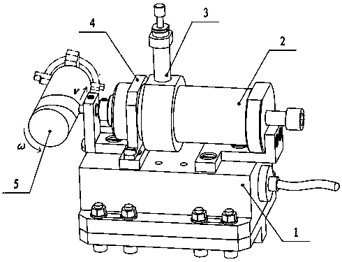
  • A friction device for solid-liquid-gas vibration-damping high-speed screw feed
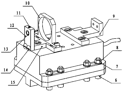
  • A friction device for solid-liquid-gas vibration-damping high-speed screw feed
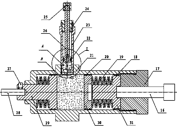
  • A friction device for solid-liquid-gas vibration-damping high-speed screw feed

Examples


Embodiment Construction

[0030] In order to facilitate the understanding of the present invention, the present invention will be described more fully below with reference to the associated drawings. Preferred embodiments of the invention are shown in the accompanying drawings. However, the present invention can be embodied in many different forms and is not limited to the embodiments described herein. On the contrary, the purpose of providing these embodiments is to make the understanding of the disclosure of the present invention more thorough and comprehensive.

[0031] Unless otherwise defined, all technical and scientific terms used herein have the same meaning as commonly understood by one of ordinary skill in the technical field of the invention. The terminology used herein in the description of the present invention is only for the purpose of describing specific embodiments, and is not intended to limit the present invention.

[0032] refer to figure 1 As shown, a solid-liquid-gas vibration-...


PUM


Abstract

The invention relates to the technical field of high-speed cutting and discloses a solid-liquid-gas damping type high-speed-spiral-feeding friction device. A knife material rod is arranged on a load-adjusting damping component, the end of the knife material rod corresponds to a rotating friction member in position, the load-adjusting damping component can adjust load received by the knife material rod and perform solid damping to drive the knife material rod to be in rotating friction with the rotating friction member, and simulation of knife-chip friction working conditions is realized; an oil-gas-injection locking component injects hydraulic oil into the load-adjusting damping component for liquid damping, and air bubbles generated during injecting also play a role in damping; a dynamometer can measure axial force and radial force received by the knife material rod, and friction factors can be obtained after converting the axial force and the radial force. By using the solid-liquid-gas damping type high-speed-spiral-feeding friction device, high-speed and high-temperature working conditions during high-speed cutting can be simulated, vibration during a high-speed friction experiment can be inhibited, adjustable load can be provided, high-speed friction factors and friction interface temperature of a knife and a workpiece material can be obtained, and knife-chip friction features of friction between a front knife face of the knife and a squeezing face of cutting chips which newly flow in can be reflected.

Description

technical field [0001] The invention relates to the technical field of high-speed cutting, and more specifically relates to a solid-liquid-gas vibration-damping friction device for high-speed screw feed. Background technique [0002] High-speed cutting is one of the mainstream technologies for material removal processing. It has the advantages of high efficiency, high quality and low cost. And the high-speed cutting technology is widely used in the emerging mold industry, thus promoting the development of modern machinery manufacturing. [0003] The realization and wide application of technology have promoted people's in-depth research on the mechanism of high-speed cutting, and at the same time, the realization of technology has also provided the material basis and experimental conditions for the study of high-speed cutting mechanism. Tool-chip friction is one of the two basic behaviors of high-speed cutting, and has always been the focus of cutting mechanism research. In...

Claims


Application Information

Patent Timeline
Patent Type & Authority Patents(China)
IPC IPC(8): B23Q17/09B23Q11/00
CPCB23Q11/0032B23Q17/0966
Inventor 徐道春李清青刘春剑郝沫涵
Owner BEIJING FORESTRY UNIVERSITY
Learn More