
Novel adjustable grinding machine

An adjustable and new technology, applied in the direction of grinding machines, grinding machine parts, grinding/polishing equipment, etc., can solve the problems of unfavorable long-term use of machinery, reduce the service life of grinding machines, increase production costs, etc., and achieve convenient position fixing and Workspace setting, flexible and convenient work, and the effect of improving work efficiency

Inactive Publication Date: 2016-06-08
TIANJIN JUXINGXIANGHAI MACHINERY CO LTD
View PDF5 Cites 2 Cited by
  • Summary
  • Abstract
  • Description
  • Claims
  • Application Information

AI Technical Summary

Problems solved by technology

[0003] But existing grinder equipment still has some deficiencies to a certain extent, and both existing this grinder equipment just utilizes the movement of grinding wheel to grind the fixed element to be polished, so the requirement and design quality of grinding wheel are very high, and also It will cause the grinding wheel to be unsteady and only to be polished. The second is to perform grinding in the process of continuous movement. Secondly, the existing equipment of this kind is all static work, and it is not possible to pre-set the program for grinding the equipment. In order to seek higher quality grinding, in the end, the existing grinding equipment produces a large vibration during grinding, which is easy to cause damage to the grinding machine, reduces the service life of the grinding machine, and increases the production cost, which is not conducive to the long-term use of the machine. It is urgent to seek a new type of grinding machine equipment

Method used


Image

  • Novel adjustable grinding machine

Examples


Embodiment Construction

[0013] In order to further understand the content, characteristics and effects of the present invention, the following examples are given in detail as follows:

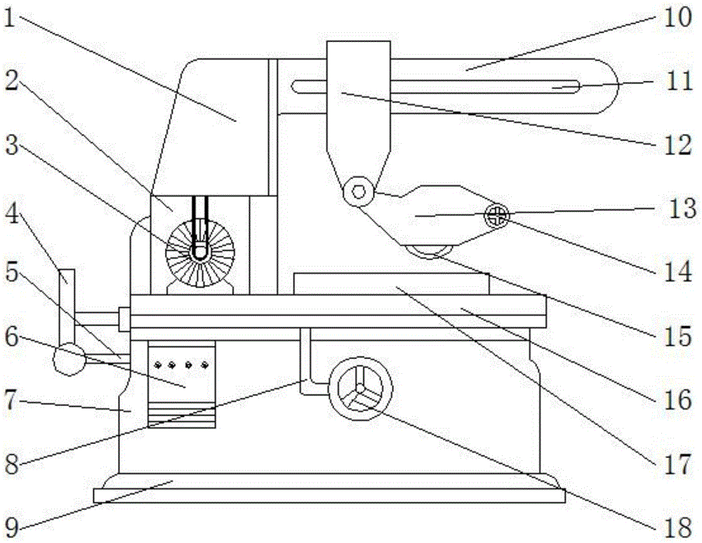
[0014] See figure 1 , the present invention includes a transmission center 1, a motor chamber 2, a motor 3, a handle 4, a push-pull rod 5, a control panel 6, a bed 7, a workbench upper and lower circulation device 8, a machine base 9, a fixed beam 10, a moving groove 11, Movers 12, grinding wheel device 13, hand control wheel 14, grinding wheel 15, workbench 16, electromagnetic sucker 17 and fixed wheel 18. in,

[0015] The transmission center 1 is respectively connected to the motor 3 and the mover 12 through a belt, and the transmission center 1 is located on the upper side of the motor 3, the engine room 2 is located on the lower side of the transmission center 1, the motor 3 is arranged inside the engine room 2, and the motor 3 is fixed on the bed 7, the handle 4 is connected to the push-pull rod 5, the push-pul...


PUM


Abstract

The invention belongs to the technical field of polishing machinery, and particularly relates to a novel adjustable grinding machine which comprises a transmission center, an engine chamber, a motor, a handle, a push-pull rod, a control panel, a bed body, a workbench up-down circulating device, a machine base, a fixing cross beam, a moving groove, a moving device, an abrasive wheel device, a manually controlled wheel, an abrasive wheel, a workbench, an electromagnetic chuck and a fixed wheel, wherein the transmission center is connected with the motor and the moving device via belts; the engine chamber is arranged under the transmission center; the motor is arranged in the engine chamber; the handle is connected with the push-pull rod; the push-pull rod is connected with the workbench; the workbench up-down circulating device is connected with the workbench and the fixed wheel; and the moving device is erected on the fixing cross beam. The novel adjustable grinding machine has the advantages that a to-be-ground element can be fixed more firmly; damage of vibration generated in a polishing process on the grinding machine can be avoided; and due to the design of working elements, the novel adjustable grinding machine is more convenient to use, and the work efficiency of the novel adjustable grinding machine is greatly improved.

Description

technical field [0001] The invention belongs to the technical field of grinding machines, in particular to a novel adjustable grinding machine. Background technique [0002] With the development of society, people pay more and more attention to the texture of the surface of the material. At this stage, the society is seeking a breakthrough in appearance under the condition of the same quality. Therefore, the grinding machine used in the processing of various materials, The grinding machine can process materials with higher hardness, such as hardened steel, hard alloy, etc.; it can also process brittle materials, such as glass and granite. Grinding machines can perform grinding with high precision and small surface roughness, as well as high-efficiency grinding, such as powerful grinding. Therefore, many grinding machines of different models and qualities have been developed in the society. [0003] But existing grinder equipment still has some deficiencies to a certain exte...

Claims


Application Information

Patent Timeline
Patent Type & Authority Applications(China)
IPC IPC(8): B24B55/00B24B45/00B24B27/00
CPCB24B55/00B24B27/0084B24B45/00
Inventor 崔振祥
Owner TIANJIN JUXINGXIANGHAI MACHINERY CO LTD
Learn More