
Rail snow remover

A technology for snow removal vehicles and tracks, which is applied in the field of track snow removal vehicles and snow removal vehicles for cleaning snow on the surface of railway tracks, can solve problems such as inapplicability, and achieve the effects of good effect, high efficiency and fast snow removal speed.

Active Publication Date: 2016-06-08
CHINA RAILWAYS CORPORATION +1
View PDF7 Cites 7 Cited by
  • Summary
  • Abstract
  • Description
  • Claims
  • Application Information

AI Technical Summary

Problems solved by technology

But it is not suitable for cleaning the snow accumulated between the track surface and the track bed, and there is no other machine for cleaning the snow between the rail surface and the track bed

Method used


Image

  • Rail snow remover
  • Rail snow remover
  • Rail snow remover

Examples


Embodiment 11

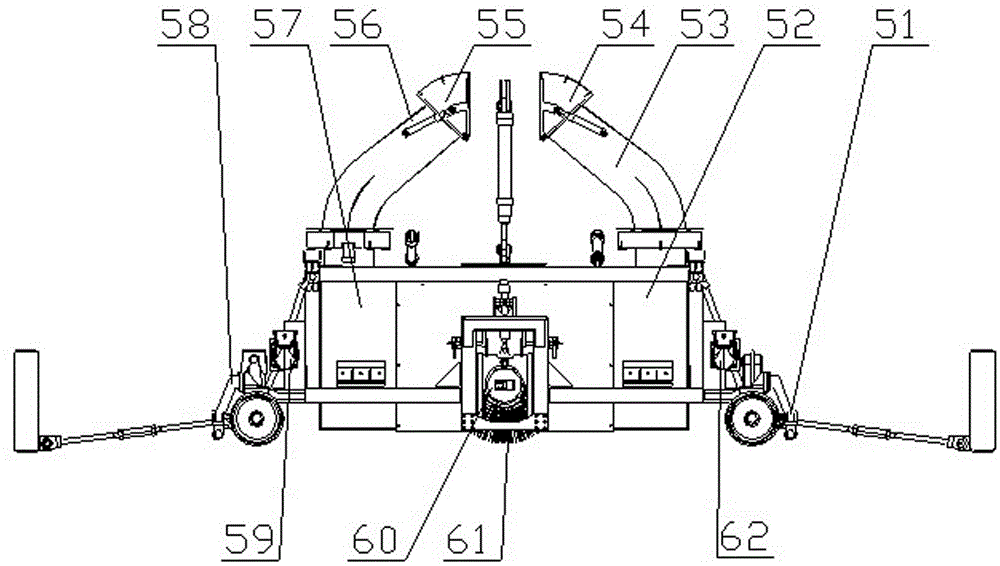
[0037] Example 1.1, the present embodiment provides a track snow removal vehicle, which includes a vehicle frame 12, which is symmetrical about its transverse central axis, and a brush-throwing snow removal device is installed in the middle of the vehicle frame 12, and the brush-throwing snow removal device is pulled by the right side. The rod 40 and the left drawbar 34 are respectively connected to the vehicle frame 12. The right driver's cab 11 is installed on the right side of the upper part of the vehicle frame 12, and the right power room 15 is installed at the rear of the right driver's cab 11. The right engine 16 is housed in the room 15, the right side below the vehicle frame 12 is connected to the upper part of the right support 44, and the bottom of the right support 44 is connected to the rear crossbeam of the right snow shovel 45 through hinged joints. The upper part of the snow shovel 45 is connected to the lower bottom surface of the vehicle frame 12 through the...

Embodiment 12

[0046] Example 1.2 , track snow removal vehicle, same as embodiment 1.1, the difference is that: when no snow removal operation is carried out for a long time, the brush-throwing snow removal device is directly removed, and when the track snow removal vehicle is used as a rail car, the right side engine 16 is driven by the right side hydraulic power. The torque converter 41 and the right transmission shaft 42 drive the right bogie 43 to provide traction and travel power; the left engine 22 drives the left bogie 31 through the left hydraulic torque converter 33 and the left transmission shaft 32 to provide traction and travel at the same time power. Also can be that any set of two sets of power systems provides traction and walking power, and the other set does not use.

Embodiment 13

[0047] Example 1.3, The track snow removal vehicle, with embodiment 1.1, is different in that: transfer case 23, hydraulic pump 24, left side power room 25 and hydraulic oil tank 26 are installed in the inside of right side power room 15.


PUM


Abstract

A rail snow remover comprises a remover frame (12). The remover frame (12) is symmetric about the transverse center axis of the remover frame (12). A brushing and throwing type snow removing device is installed in the middle portion of the remover frame (12) and connected with the remover frame (12) through a traction rod. A cab is arranged on the right side of the upper portion of the remover frame (12). A power room is arranged at the rear portion of the cab and internally provided with an engine. A snow pushing shovel is connected to the right side below the remover frame (12) through a support. The upper portion of the snow pushing shovel is connected to the lower bottom face of the remover frame (12) through a lifting oil cylinder I. A right suspension (48) is fixed to the upper portion of the snow pushing shovel. The position above the right suspension (48) is connected with the bottom of the remover frame (12). Locking limiting pins are arranged at the lower portion of the right suspension (48). An exhaust hood is arranged at the top of the power room. The rail snow remover can remove snow both on the left side and the right side, accumulated snow between the position higher than the surface of a steel rail by a certain depth of and a rail bed slab at the bottom, the snow can be thrown to any side of the rail in the snow removing process, and the snow throwing distance can be adjusted. The rail snow remover has the beneficial effects of being high in snow removing speed and efficiency and good in effect.

Description

technical field [0001] The invention relates to a track snow removal vehicle, in particular to a snow removal vehicle for clearing snow on the surface of railway tracks, and belongs to the technical field of engineering equipment. Background technique [0002] There are a large number of railways in the northern part of my country. In winter, snowfall will bury the railways. Due to the low temperature, the snow usually does not melt for dozens of days or even months. The existence of snow, on the one hand, affects the safe operation of trains, and on the other hand, it makes it impossible for construction workers to check the status of rails and fasteners, resulting in potential safety hazards on the line. [0003] At present, there are no special locomotives used for track snow removal in China. Manual cleaning is the only way. The labor load is high, the labor intensity is high, and the cleaning takes a long time. In addition, the density of trains is high, and the safety ...

Claims


Application Information

Patent Timeline
Patent Type & Authority Applications(China)
IPC IPC(8): E01H8/06
Inventor 郭关柱陶小虎李海昆张峥明张衔陈松雷广鹏王晓东袁飞宇王平
Owner CHINA RAILWAYS CORPORATION
Learn More