
Connecting joint for outer sleeve pipe type concrete filled steel tubular column and steel girder end plate

A technology of steel pipe concrete columns and connection nodes, which is applied in the direction of construction and building construction, can solve the problems of steel pipe column wall node damage, etc., and achieve the effects of reduced construction costs, high initial stiffness and bending bearing capacity, and superior deformation performance

Inactive Publication Date: 2016-06-08
GUANGZHOU UNIVERSITY
View PDF9 Cites 1 Cited by
  • Summary
  • Abstract
  • Description
  • Claims
  • Application Information

AI Technical Summary

Problems solved by technology

[0005] The purpose of the present invention is to provide an outer sleeve type steel pipe concrete column and steel beam unilateral end plate connection node, which has simple structure, clear force transmission, convenient structure layout, fast construction, and solves the problem of high-strength bolts in the node area where the construction of steel pipe columns is difficult. The wall has been convexly deformed to cause the problem of node damage, and there is no need for on-site welding, and it is easy to disassemble and replace

Method used


Image

  • Connecting joint for outer sleeve pipe type concrete filled steel tubular column and steel girder end plate
  • Connecting joint for outer sleeve pipe type concrete filled steel tubular column and steel girder end plate
  • Connecting joint for outer sleeve pipe type concrete filled steel tubular column and steel girder end plate

Examples


Embodiment Construction

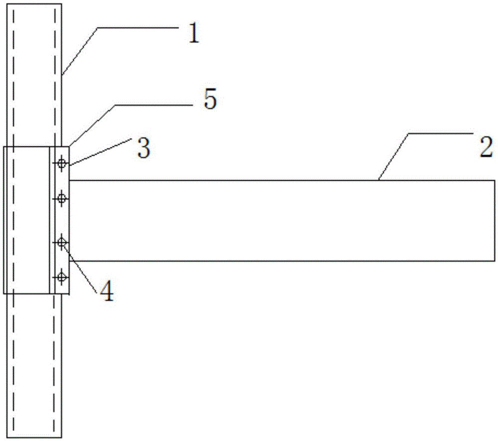
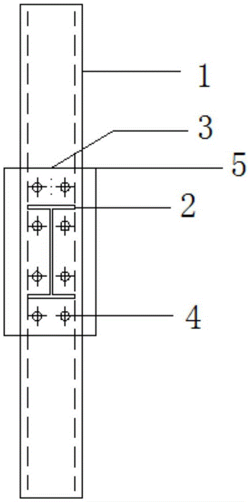
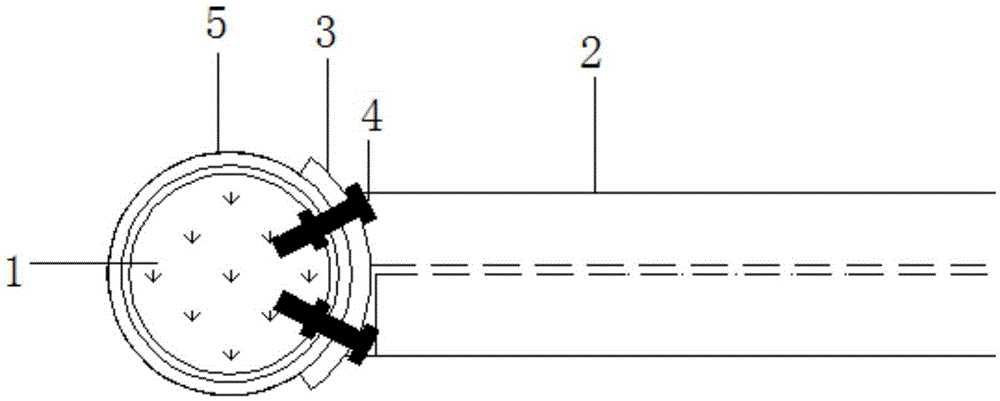
[0024] Such as Figure 1a ~ Figure 1d As shown, the connection node between CFST column and steel beam includes CFST column 1, steel beam 2, end plate 3, one-way self-tightening bolt 4, outer sleeve 5, and the edge of outer sleeve 5 is welded between steel beam and CFST column 1. Outer side of the lap joint of the steel pipe column wall, the end plate 3 is located outside the outer sleeve 5; the section of the steel beam 2 is H-shaped or I-shaped, and its end is welded on the end plate 3; the high-strength one-way self-tightening bolt 4 is from the outer And insert the end plate 3, the outer casing 5 and the bolt hole reserved in the steel pipe wall of the steel pipe concrete column 1, and the bolt head of the one-way self-tightening bolt 4 has a self-supply function, and forms a riveting head on the inner side of the steel pipe concrete column 1; Concrete is poured inside the steel tube concrete column 1 to form a steel tube concrete column-steel beam connection node.

[002...


PUM


Abstract

The invention discloses a connecting joint for an outer sleeve pipe type concrete filled steel tubular column and a steel girder end plate. The connecting joint comprises the concrete filled steel tubular column, a steel girder, an end plate, high-strength unidirectional self-fastening bolts and an outer sleeve pipe, wherein the edge of the outer sleeve pipe is welded to the outer side of a steel tubular column wall in the lap joint position of the steel girder and the concrete filled steel tubular column, and the end plate is located on the outer side of the outer sleeve pipe; the end of the steel girder is welded to the end plate; the unidirectional self-fastening bolts are inserted into bolt holes reserved in the end plate, the outer sleeve pipe and the steel tubular column wall from outside to inside; the heads of the unidirectional self-fastening bolts have a self-supply function, and riveting heads are formed on the inner side of the concrete filled steel tubular column; concrete is poured into the concrete filled steel tubular column. The connecting joint has good stress and anti-seismic properties, is simple in structure, definite in force transmission and fast in construction and facilitates structure layout. The problems that high-strength bolts are difficult to construct in a joint area, and the steel tubular column wall at the connecting joint of the unidirectional self-fastening bolts is prone to protrude outwards and deform due to lack of protection are solved. The connecting joint is a novel semi-rigidity connecting joint for the concrete filled steel tubular column and the steel girder.

Description

technical field [0001] The invention belongs to the field of connection nodes of structural engineering, and in particular relates to a connection node of an outer casing type concrete filled steel pipe column and a steel beam end plate. technical background [0002] Before the 1980s, most of the high-rise buildings in my country used reinforced concrete structures. However, with the increase in height and number of floors, the use of building functions has become increasingly complex. Concrete structures or pure steel structures can no longer meet the requirements of functional functions. Facing the huge challenge of high-rise and super-high-rise buildings, concrete-filled steel tube structures are increasingly being used in high-rise building structures due to their excellent performance. However, the research on joints between concrete filled steel tubes and steel beams is far less thorough than the research on joints between steel columns and steel beams. Therefore, rese...

Claims


Application Information

Patent Timeline
IPC IPC(8): E04B1/58
Inventor 刘坚周观根高奎王永梅任达毛捷方颖强李高辉
Owner GUANGZHOU UNIVERSITY
Learn More