Gas pressure reduction valve

A valve and gas technology, used in safety valves, balance valves, valve devices, etc., can solve the problems of low pressure regulation accuracy, poor operating stability, and small pressure regulation range, and achieve convenient uniformity, simple structure, and controllable points. many effects

Inactive Publication Date: 2016-06-08
CHENGDU KESHENG PETROLEUM TECH
View PDF3 Cites 5 Cited by
  • Summary
  • Abstract
  • Description
  • Claims
  • Application Information

AI Technical Summary

Problems solved by technology

[0004] The decompression performance of the above-mentioned existing decompression valves with any structure is greatly affected by the springs installed therein, and the processing accuracy of the springs and the controllability of the change in mechanical properties during use are poor. In this way, the traditional high-pressure gas decompression The valve has a small range of pressure regulation, low pressure regulation accuracy, and poor stability in use. The invention provides a gas decompression valve

Method used


Image

  • Gas pressure reduction valve

Examples


Embodiment 1

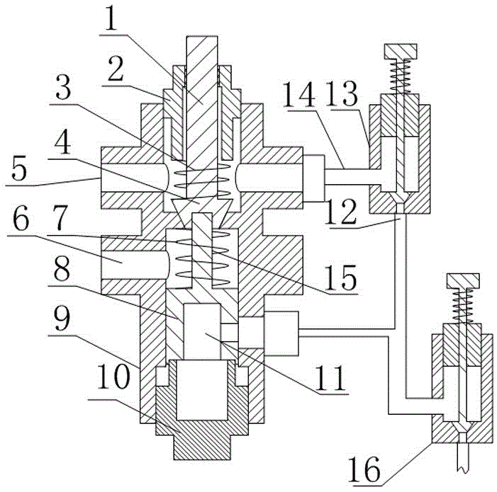
[0025] Such as figure 1 As shown, a gas decompression valve includes a valve body 9, an inlet passage 5 and an outlet passage 6 are arranged on the valve body 9, and a decompression part communicating with the inlet passage 5 and the outlet passage 6 is arranged in the valve body 9, so The decompression part includes a valve core 4 and a valve seat arranged on the valve body 9, the valve body 9 is also screwed with a pressure seat 2, and a first spring 3 is arranged between the pressure seat 2 and the valve core 4, and also includes an adjustment The valve and the piston chamber 11 arranged in the valve body 9, the piston chamber 11 is arranged on the side of the decompression part close to the outlet passage 6, the piston chamber 11 is also provided with a piston 8, and the piston 8 is near the side of the valve core 4 One side is provided with a connecting rod 15 for fixedly connecting the piston 8 and the valve core 4, the intake end of the regulating valve communicates wit...

Embodiment 2

[0032] The present embodiment is further limited on the basis of embodiment 1, as figure 1 As shown, in order to reduce the change speed of the channel area for gas flow between the valve core 4 and the valve seat during the movement of the valve core 4, that is, to improve the controllability of the flow channel area, the valve seat and the valve core 4 The sections are conical, and the valve seat and the larger end of the valve core 4 are close to the inlet channel 5 . The above structure also facilitates the sealing of the valve core 4 and the valve seat in the shut-off state of the present invention.

[0033] In order to improve the uniformity of the force on the valve core 4 and further ensure and improve the output pressure accuracy of the present invention, the axis of the first spring 3 is collinear with the axis of the guide rod 1 .

[0034] In order to facilitate the processing, assembly and maintenance of the present invention, the valve body 9 is provided with a s...

Embodiment 3

[0037] This embodiment is further limited on the basis of the above embodiments, as figure 1 As shown, in order to optimize the flow adjustment performance of the pressure regulating valve 13 and the relief valve 16, both the regulating valve and the relief valve 16 are cut-off valves.

[0038] In order to further optimize the above-mentioned flow adjustment performance, the sealing surface of the cut-off valve is tapered.


PUM


Abstract

The invention discloses a gas pressure reduction valve which comprises a valve body. The valve body is provided with an inlet channel and an outlet channel. A pressure reduction part is arranged in the valve body and comprises a valve core and a valve seat, the valve body is further in threaded connection with a pressure base, and a first spring is arranged between the pressure base and the valve core. The gas pressure reduction valve further comprises a regulating valve and a piston cavity, a piston is further arranged in the piston cavity, one side of the piston close to the valve core is provided with a connecting rod, and an outlet connecting pipe is further provided with a discharge valve. One side of the valve core close to the inlet channel is further fixedly connected with a guide rod, the pressure base or the valve body is provided with a hole in clearance fit with the guide rod, a gap between the hole and the guide rod is not larger than 0.5 mm, and the gap is axially sealed through at least one O-shaped ring. A second spring with the two ends in contact with the valve seat and the piston respectively are further arranged between the valve seat and the piston. The gas pressure reduction valve is simple in structure, long in service life and high in air outlet pressure regulation precision.

Description

technical field [0001] The invention relates to the field of compressed gas decompression devices, in particular to a gas decompression valve. Background technique [0002] As natural gas is used more and more widely, various forms of pressure reducing valves emerge in endlessly. Further optimization of the structure of natural gas pressure reducing valves will further promote the use of natural gas. Taking environmental awareness as an example, the use of natural gas as fuel for vehicle engines can greatly reduce vehicle exhaust pollution. However, in order to improve the single inflation stroke of vehicles fueled by natural gas, high-pressure gas cylinders are installed on vehicles to accommodate natural gas. The pressure of the natural gas introduced into the cylinder is generally several thousand pascals. In this way, the pressure reducing valve for reducing the pressure of high-pressure natural gas is particularly important. In terms of power and even driving safety. ...

Claims


Application Information

Patent Timeline
Patent Type & Authority Applications(China)
IPC IPC(8): F16K17/20
CPCF16K17/20
Inventor 贺昶明唐小洪
Owner CHENGDU KESHENG PETROLEUM TECH
Why Eureka
Try Eureka