High-rotation speed and large-torque brake motor test bench

A brake motor and high torque technology, applied in the field of test equipment, can solve the problems that it is difficult to meet the detection requirements of high speed and high torque, and achieve the effect of easy installation and debugging, and easy analysis and research

Inactive Publication Date: 2016-06-08
ANHUI WEINENG MOTOR
View PDF5 Cites 17 Cited by
  • Summary
  • Abstract
  • Description
  • Claims
  • Application Information

AI Technical Summary

Problems solved by technology

Ordinary inertia wheel brake motor test bench is difficult to meet the detection requirements of high speed and high torque

Method used


Image

  • High-rotation speed and large-torque brake motor test bench
  • High-rotation speed and large-torque brake motor test bench
  • High-rotation speed and large-torque brake motor test bench

Examples


Embodiment Construction

[0013] The present invention will be further described below in conjunction with the accompanying drawings.

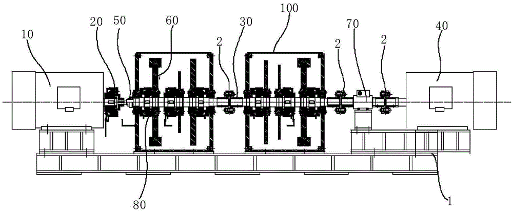
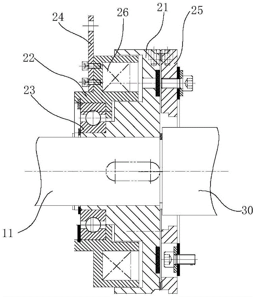
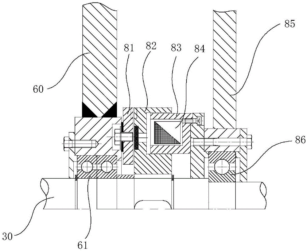
[0014] to combine figure 1 , 2 , high speed and high torque brake motor test bench, the motor shaft 11 of the driving motor 10 is connected to one end of the load shaft 30 by the first electromagnetic clutch 20, and the other end of the load shaft 30 is connected to the brake motor 40 to be tested by a coupling A speed sensor 50 , a load flywheel disc 60 , and a torque sensor 70 are sequentially connected to the load shaft 30 in the direction from the drive motor 10 to the brake motor 40 to be tested.

[0015] The driving motor 10 is a variable frequency speed regulating motor, connected with the load shaft 30 through the first electromagnetic clutch 20, and can realize dynamic disengagement during operation, so as to eliminate the influence of the rotor kinetic energy of the driving motor 10 on the experiment. The speed sensor 50 feeds back the rotational speed sign...


PUM


Abstract

The invention relates to a high-rotation speed and large-torque brake motor test bench. The motor shaft of a driving motor is connected with one end of a load rotation shaft through a first electromagnetic clutch; the other end of the load rotation shaft is connected with a motor to be tested through a coupling; a speed testing sensor, load flywheel discs and a torque sensor are sequentially connected onto the load rotation shaft from the driving motor to the motor to be tested; a variable-frequency and variable-speed motor is adopted as the driving motor; and the driving motor is connected with the load flywheel discs through the electromagnetic clutch. In the operating process of the system, dynamic disconnection can be realized, so that the influence of the kinetic energy of the rotor of the driving motor on a test can be eliminated; a computer transmits signals to a PLC according to rotational inertia required by the test, so that the electromagnetic clutch mechanism can be controlled. The maximum torque of the test bench can reach 2000N*m, and the maximum rotation speed of the test bench can reach 3500rpm. In the design process of the system, a computer control system simple and easy to operate is adopted, and a safe and reliable PLC interlocking detection system is adopted; and output data are processed by the computer, and an intuitive curve graph can be drawn, and therefore, the analysis research of product performance can be facilitated.

Description

technical field [0001] The invention relates to test equipment, in particular to a high-speed and high-torque braking motor test bench. Background technique [0002] Braking motors are generally used in gravity lifting equipment such as elevators and cranes, and their braking performance determines the safe operation of the equipment. The brake motor test bench is mainly used to detect the braking performance of the brake motor, which is of great significance for controlling the quality of the brake motor and studying the improvement of product structure and performance. [0003] There are many types of brake motors, and it is difficult to detect. The standard product speed range is generally 750rpm to 3000rpm, and its braking torque range is generally 7.5N*m to 1500N*m. Ordinary inertia wheel brake motor test bench is difficult to meet the detection requirements of high speed and high torque. Contents of the invention [0004] The purpose of the present invention is to ...

Claims


Application Information

Patent Timeline
Patent Type & Authority Applications(China)
IPC IPC(8): G01R31/34
CPCG01R31/34
Inventor 吴赛飚李利娟张立飞吴浩亮张世俊汪小兴
Owner ANHUI WEINENG MOTOR
Why Eureka
Try Eureka