Drum type chip burning equipment

A burning equipment, drum-type technology, applied in the direction of conveying record carriers, instruments, computer parts, etc., can solve the problems of insufficient IC placement of IC burning equipment, increasing burning time, and decreasing production speed.

Active Publication Date: 2016-06-08
王安松
View PDF9 Cites 2 Cited by
  • Summary
  • Abstract
  • Description
  • Claims
  • Application Information

AI Technical Summary

Problems solved by technology

[0004] Although the existing IC burning equipment can achieve the effect of IC burning, but because the displacement arm is a single arm and rotates in a plane, each programmer needs to wait for the displacement arm to place the IC. The effect of programming can be achieved, which leads to the disadvantage of greatly increasing the programming time, and the number of programmers that can be placed on the displacement arm is easily limited by the space, resulting in the disadvantage that the number of programmers cannot be increased, which makes the existing IC The number of ICs placed in the programming equipment is insufficient, which leads to the situation that the number of IC production cannot be increased and the production speed is reduced.

Method used


Image

  • Drum type chip burning equipment
  • Drum type chip burning equipment
  • Drum type chip burning equipment

Examples


Embodiment Construction

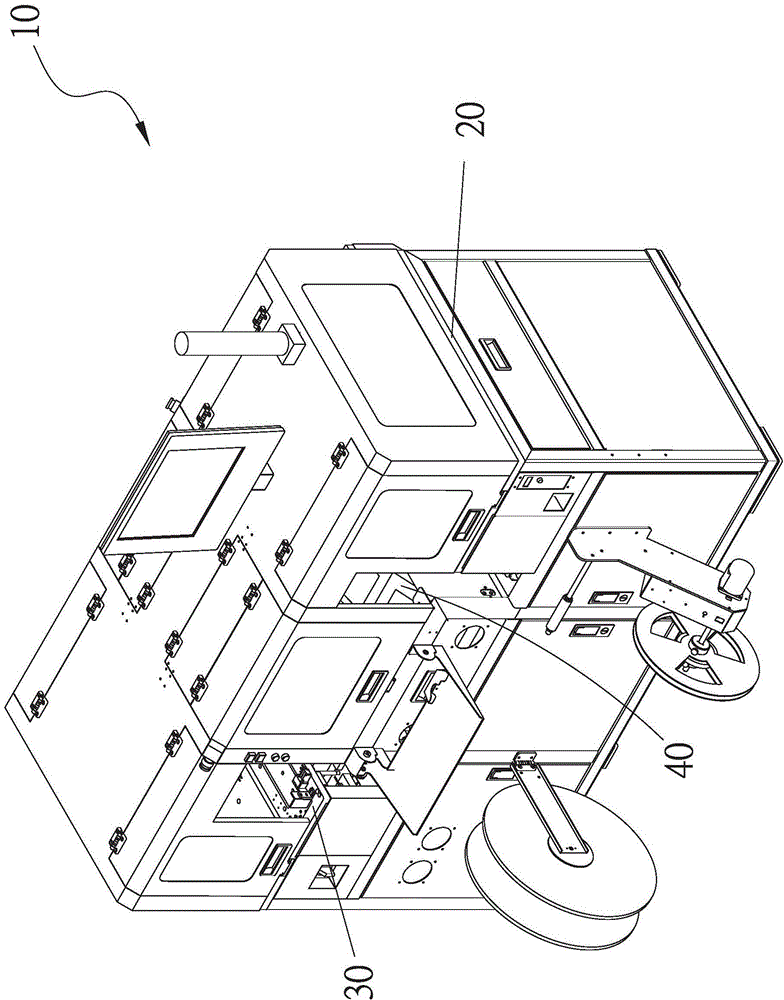
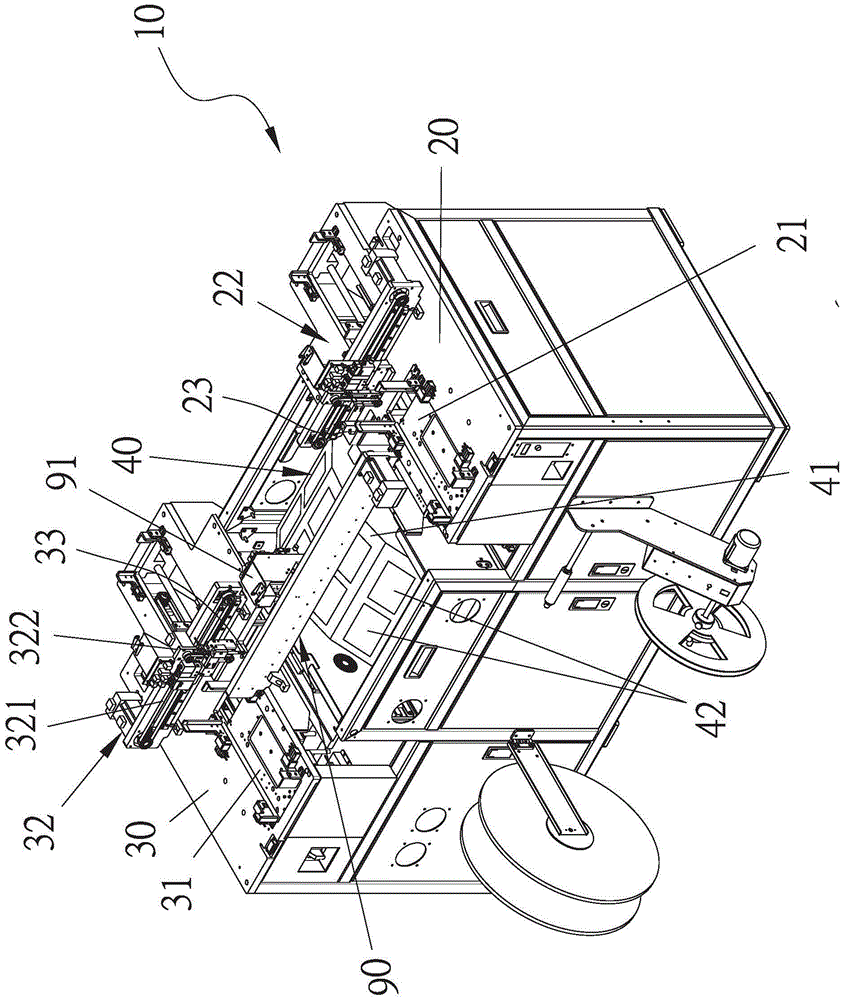
[0044] see figure 1 , figure 2 As shown, the present invention provides a drum-type chip programming device, which includes:

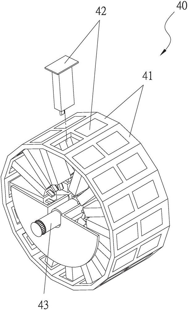
[0045] Burning equipment 10, this burning equipment 10 is provided with the first working platform 20, the second working platform 30, the drum type burning device 40, the pick-up device 90, and this first working platform 20 is provided with the material seat Moving device 202, and the first working platform 20 is provided with a first material placement part 21, and the first material placement part 21 can be arranged on the material placement seat displacement device 202, and as Figure 5 As shown, the first working platform 20 is provided with a feeding device 22, and the feeding device 22 is provided with a lateral displacement device 221, and the lateral displacement device 221 is provided with a longitudinal displacement device 222, and the longitudinal displacement device 222 is provided with a second A feeding suction nozzle 23, and as Fi...


PUM


Abstract

The invention relates to drum type chip burning equipment comprising a burning unit. A first working platform, a second working platform, a drum type burning device, and a material taking device are arranged in the burning unit; a material placing part and a feeding device are arranged at the first working platform; and a conveying device is arranged on the second working platform. The drum type burning device is arranged between the first working platform and the second working platform by a shaft; a plurality of plane parts are arranged at the drum type burning device in an annular mode; and at least one burning machine is arranged at each plane part. According to the invention, the multiple plane parts are arranged at the drum type burning device in an annular mode and each plane part is provided with at least one burning machine; and the drum type burning device is arranged between the first working platform and the second working platform by the shaft. The feeding device can place ICs without burning processing in sequence and the conveying device can take ICs with completed burning in sequence. Therefore, an effect of increasing of the number of placed ICs can be realized by using the drum type burning device and thus the produced number can be increased; and an objective of boosting of the production speed can be achieved.

Description

technical field [0001] The invention relates to a chip burning device, especially a drum-type chip burning device capable of increasing the number of IC chips placed. Background technique [0002] When the existing programming equipment picks and places the IC on the robotic arm, the linear motion X-axis is carried by the linear motion Y-axis. After performing horizontal coordinate positioning, the linear motion Z-axis carried by the Y-axis performs vertical pick-up or placement of the IC. Afterwards, the X and Y motion axes move to another horizontal coordinate, and then the Z axis performs vertical pick-up or placement of the IC. Such sequential actions, because the existing three-axis system cannot process the operating program in parallel, in It greatly affects the production speed, and the existing programming equipment is set to detect the position deviation of the IC before it is placed in the programmer, all of which use the image recognition component, which not onl...

Claims


Application Information

Patent Timeline
Patent Type & Authority Applications(China)
IPC IPC(8): G06K13/07
Inventor 王安松翁庆昌
Owner 王安松
Why Eureka
Try Eureka