
Magnetic resonance temperature imaging method and system

An imaging method and magnetic resonance image technology, applied in medical science, diagnostic signal processing, sensors, etc., can solve problems such as image deformation, image distortion, and low time resolution

Active Publication Date: 2016-06-15
SHENZHEN INST OF ADVANCED TECH CHINESE ACAD OF SCI
View PDF7 Cites 8 Cited by
  • Summary
  • Abstract
  • Description
  • Claims
  • Application Information

AI Technical Summary

Problems solved by technology

On the one hand, to image a large area near the target tissue, layer-by-layer scanning or three-dimensional imaging is required, which takes a long time to scan and has low time resolution, so real-time temperature monitoring cannot be realized.
[0005] GRE-EPI sequence image acquisition can speed up image acquisition, but EPI is very sensitive to factors such as magnetic field inhomogeneity and gradient system eddy current, which introduces additional distortion to the image
[0006] The MASTER sequence can also realize the acquisition of multi-layer image information in one repetition period by designing special radio frequency excitation and gradient, but this method usually leads to a longer echo time (TE), which makes the image signal-to-noise ratio decrease and is prone to Signal Loss and Image Distortion

Method used


Image

  • Magnetic resonance temperature imaging method and system
  • Magnetic resonance temperature imaging method and system
  • Magnetic resonance temperature imaging method and system

Examples


Embodiment Construction

[0051] In order to make the purpose, technical solutions and advantages of the embodiments of the present invention more clear, the embodiments of the present invention will be further described in detail below in conjunction with the accompanying drawings. Here, the exemplary embodiments and descriptions of the present invention are used to explain the present invention, but not to limit the present invention.

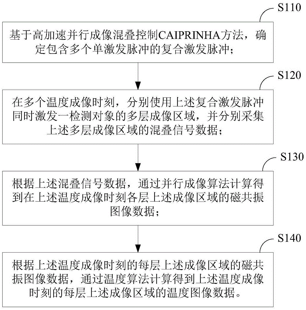
[0052] The invention provides a magnetic resonance temperature imaging method, which uses a specially designed composite pulse to simultaneously excite the multi-layer imaging region of the object to be detected, and uses a Simultaneous Multi-Slice Pulse (SMS) sequence to simultaneously collect multi-layer image signals , and a specially designed image processing method, which can simultaneously perform temperature imaging on the imaging area of ​​each layer.

[0053] figure 1 It is a schematic flowchart of a magnetic resonance temperature imaging method according to...


PUM


Abstract

The present invention provides a magnetic resonance temperature imaging method and system. The method comprises the steps of determining a compound excitation pulse including a plurality of single excitation pulses on basis of a highly accelerated parallel imaging aliasing control method; at a lot of temperature imaging moments, respectively using the compound excitation pulse to simultaneously exciting multilayer imaging areas, and respectively acquiring aliasing signal data of the multilayer imaging areas. calculating and obtaining magnetic resonance image data of each layer of the imaging areas at the temperature imaging moments by a parallel imaging algorithm according to the aliasing signal data; and calculating and obtaining temperature image data of each layer of the image areas at the temperature imaging moments by a temperature algorithm according to the magnetic resonance image data of each layer of the imaging areas at the temperature imaging moments. A lot of temperature imaging moments include an initial temperature moment before temperature changes, and the temperature image data include temperature difference between the temperature imaging moment after the temperature changes and the initial temperature moment. According to the magnetic resonance temperature imaging method and system, temperature imaging efficiency can be improved.

Description

technical field [0001] The invention relates to the technical field of magnetic resonance sequence design, in particular to a magnetic resonance temperature imaging method and system. Background technique [0002] In MRI-guided High Intensity Focused Ultrasound (HIFU) thermal ablation therapy, multiple beams of high-intensity ultrasound are converged to the focus from different directions, and the concentrated energy of the focus is huge, which can instantly cause coagulation necrosis of the tissue. Once the focus positioning is deviated , causing damage to normal tissues. Magnetic resonance temperature imaging technology is one of the keys to ensure the safety and therapeutic effect of HIFU treatment by performing temperature imaging on different positions of the target tissue in HIFU treatment. During HIFU treatment, the temperature distribution of the target tissue is constantly changing, so temperature monitoring is required to have better real-time performance. HIFU t...

Claims


Application Information

Patent Timeline
IPC IPC(8): A61B5/01A61B5/055
CPCA61B5/015A61B5/055A61B5/72A61B5/7257
Inventor 郭文莎刘新邹超帖长军
Owner SHENZHEN INST OF ADVANCED TECH CHINESE ACAD OF SCI
Learn More