
Material taking and releasing manipulator

A technology for manipulators and pick-and-place materials, applied in the direction of manipulators, program-controlled manipulators, chucks, etc., can solve the problems of uncertain personal safety of workers, impact on product quality, inaccurate positioning, etc., and achieve compact structure, low manufacturing cost, and translational movement fast effect

Active Publication Date: 2016-06-15
CHINA NAT ELECTRIC APP RES INST
View PDF7 Cites 8 Cited by
  • Summary
  • Abstract
  • Description
  • Claims
  • Application Information

AI Technical Summary

Problems solved by technology

This kind of manual loading and unloading has several disadvantages: 1. The forming area is located on the top of the vacuum box. Generally, the height of the vacuum box is more than 2 meters. Workers need to climb to the forming area on the vacuum box with the material board, and then return to the ground.
Forming a product requires workers to perform repetitive and heavy physical labor
2. There is a pressure plate above the forming area. When the vacuum forming machine is working, the pressure plate must be driven by the oil cylinder to the forming area to be pressed tightly. When the worker discharges the material plate to the forming area, the upper pressure plate will pose an uncertain threat to the personal safety of the worker.
3. When the material board is placed in the forming area, the position of the material board needs to be accurately positioned. When the worker repeats the work, the positioning may be inaccurate due to fatigue, which will affect the quality of the product

Method used


Image

  • Material taking and releasing manipulator
  • Material taking and releasing manipulator
  • Material taking and releasing manipulator

Examples


Embodiment Construction

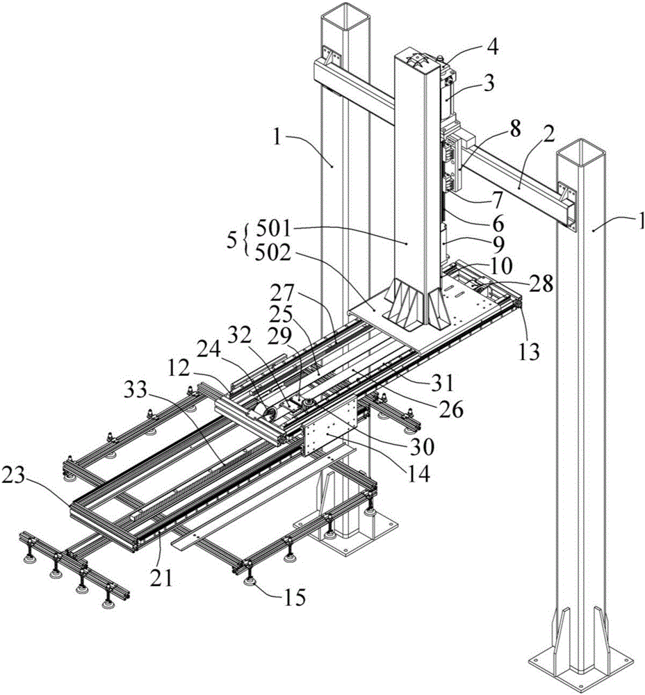
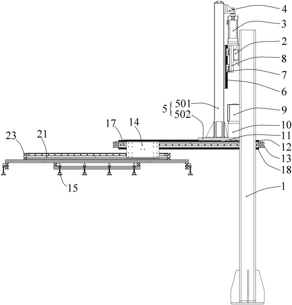
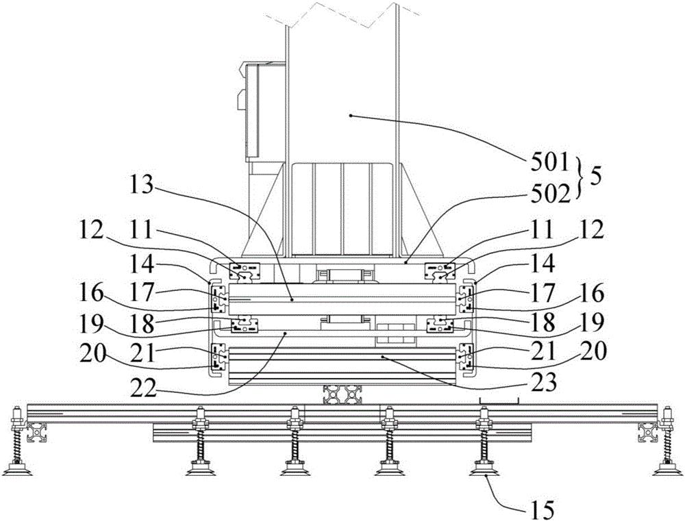
[0024] like Figure 1 to Figure 4 As shown, the pick-and-place manipulator of the present invention is composed of a frame assembly, a vertical movement assembly, a horizontal movement assembly and a suction cup assembly capable of picking up and putting down materials.

[0025] The frame assembly is composed of two support columns 1 and a crossbeam 2 connected between the two support columns 1, and the two support columns 1 can be fixed on the site where the pick-and-place manipulator is placed. The above-mentioned vertical motion assembly is provided with a cylinder 3, a connecting seat 4, a L-like bracket 5 and a first linear sliding pair, wherein the L-like bracket 5 is composed of a vertical rod part 501 and a horizontal plate connected to the lower end surface of the vertical rod part 501 502; the cylinder 3 is fixed on the beam 2, and the piston rod of the cylinder 3 is set upwards, and the upper end of the vertical rod part 501 is fixedly connected with the piston rod ...


PUM


Abstract

The invention discloses a material taking and releasing manipulator. According to the material taking and releasing manipulator, a suction cup assembly can be driven by a horizontal moving assembly to horizontally move between a material taking position and a material releasing position, a vertical moving assembly and the suction cup assembly can be used for taking materials in the material taking position and releasing the materials in the material releasing position, and thus material taking and releasing are achieved. In addition, the horizontal moving assembly provided with a first-level frame, a speed doubling plate, a second-level frame and side plates is adopted by the material taking and releasing manipulator, so that the horizontal moving assembly is divided into the upper-level frame and lower-level frame for transmission, and the horizontal moving speeds of the first-level frame, the speed doubling plate and the second-level frame are sequentially increased level by level. The material taking and releasing manipulator has the advantages that the horizontal moving speed of the suction cup assembly is high, the material taking and releasing efficiency is high, the horizontal moving assembly is compact in structure and high in stability, and the manufacturing cost is low.

Description

technical field [0001] The invention relates to a pick-and-place material manipulator, which belongs to the field of automatic home appliance assembly. Background technique [0002] The commonly used single-station vacuum forming machines now use manual loading and unloading, that is, the worker takes the material sheet from the stacking table and puts it in the forming area on the vacuum box. After the material board is formed, the workers go to the forming area to take away the formed product, and then take the material from the stacking table to form the next product. This kind of manual loading and unloading has several disadvantages: 1. The forming area is located on the top of the vacuum box. Generally, the height of the vacuum box is more than 2 meters. Workers need to climb to the forming area on the vacuum box with the material board, and then return to the ground. After the product is formed, it has to climb to the forming area to take the product back to the grou...

Claims


Application Information

Patent Timeline
IPC IPC(8): B25J9/00B25J15/06B25J9/12
CPCB25J9/0009B25J9/123B25J15/0616
Inventor 崔伟陶顺兴王宁
Owner CHINA NAT ELECTRIC APP RES INST
Learn More