Fiber cake grabbing fixture and automatic fiber cake stacking system and method

A jig and silk cake technology, applied in the stacking of objects, destacking of objects, conveyor objects, etc., can solve problems such as low efficiency, and achieve the effect of improving stacking efficiency, reducing weight and reducing labor intensity.

Inactive Publication Date: 2019-06-07
KEDA INDUSTRIAL GROUP CO LTD
View PDF9 Cites 4 Cited by
  • Summary
  • Abstract
  • Description
  • Claims
  • Application Information

AI Technical Summary

Problems solved by technology

[0005] This kind of automatic grabbing device meets the grabbing and handling operations of a single silk cake at a time, but it is used in the palletizing process with a large workload, and the efficiency is low. The palletizing method in the prior art is: first, the The silk cake placed on the wire car is removed from the wire car, and then transferred to the designated stacking area and stacked layer by layer, and the adjacent two sides are separated by partitions (hard corrugated paper)

Method used


Image

  • Fiber cake grabbing fixture and automatic fiber cake stacking system and method
  • Fiber cake grabbing fixture and automatic fiber cake stacking system and method

Examples


Embodiment 1

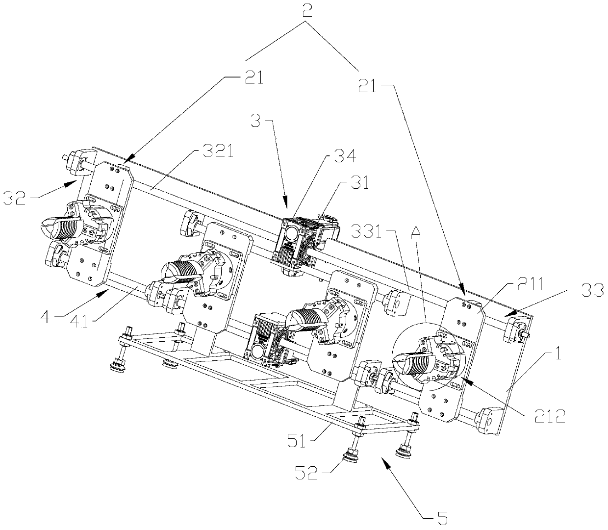
[0054] refer to figure 1 , the present embodiment discloses a fiber cake grabbing jig, including a jig bottom plate 1, at least one jaw set 2 and a drive assembly 3 corresponding to each jaw set 2 are arranged on the jig bottom plate 1, and the jaw set 2 It includes two gripper assemblies 21 arranged at intervals, and the drive assembly 3 drives the two gripper assemblies 21 to approach or move away from each other at the same time. In this embodiment, two sets of jaw sets 2 are provided.

[0055] Each clamp assembly 21 includes a clamp base 211 and a wire extraction assembly 212 , and the wire extraction assembly 212 is disposed on the clamp base 211 .

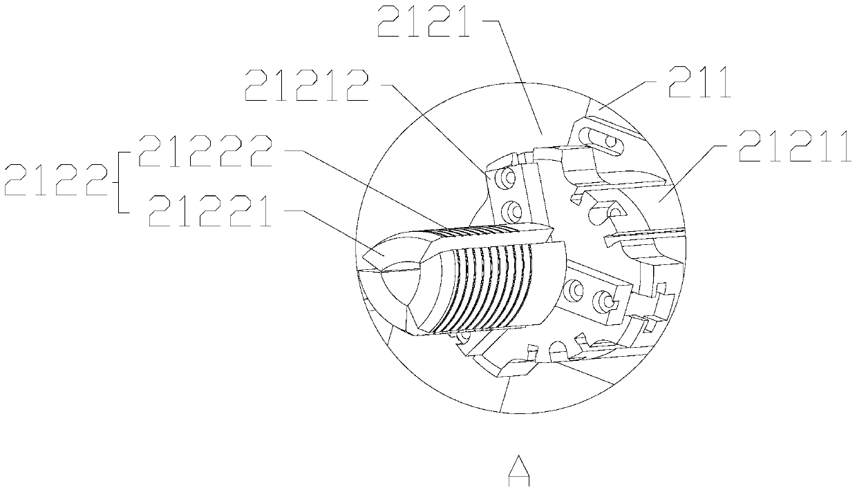
[0056] refer to figure 1 and figure 2 , each wire taking assembly 212 includes a three-jaw air claw 2121 and three jaws 2122, the three-jaw air claw 2121 is a parallel opening and closing type three-jaw air claw 2121, and the three-jaw air claw 2121 includes an air claw seat 21211 and three The air claw 21212 arranged on ...

Embodiment 2

[0071] Based on Embodiment 1, this embodiment discloses another fiber cake grabbing fixture, which is different from Embodiment 1 in that the drive assembly of this embodiment is a telescopic element, and the telescopic element is a hydraulic telescopic cylinder or a pneumatic telescopic cylinder. Each clamp assembly is correspondingly provided with a telescopic piece, and the expansion and contraction direction of the telescopic piece is parallel to the moving direction of the clamp assembly.

Embodiment 3

[0073] Based on the above embodiments, this embodiment discloses an automatic yarn cake palletizing system, including a palletizing robot and a fiber cake grabbing jig in any of the above embodiments.


PUM


Abstract

The invention discloses a fiber cake grabbing fixture and an automatic fiber cake stacking system. The grabbing fixture comprises a fixture base plate; at least one clamping jaw set is arranged on thefixture base plate; each clamping jaw set comprises two fixture modules arranged at intervals; each fixture module comprises a fixture base and a fiber taking module; each fiber taking module is arranged on each fixture base; the fixture base plate is provided with driving modules corresponding to the clamping jaw sets; the driving modules drive two fixture modules in the same clamping jaw set toapproach or leave from each other; the grabbing fixture is provided with the driving modules corresponding to the clamping jaw sets; the driving module can synchronously drive the two fixture modulesin the same clamping jaw set to approach or leave from each other, so that a gap between the fixture modules is conveniently adjusted to meet the gap change demands of fiber cakes in the fiber cake taking and placing process, and the fiber cake stacking efficiency is improved; and the invention provides the automatic fiber cake stacking system and stacking method to achieve effective improvementof the stacking efficiency, high reliability and reduction of the labor intensity.

Description

technical field [0001] The invention relates to the field of logistics packaging, in particular to a fiber cake grabbing jig, an automatic yarn cake stacking system and a method. Background technique [0002] At present, in the fiber manufacturing and packaging industry, most enterprises use manual methods in the process of packaging or transshipment of finished silk cakes. The specific process is as follows. The silk cakes are first off the machine and spun on the silk car, and then they are cut, drawn, inspected, Grading and other links, and finally transferred to the packaging area for packaging and sale. [0003] The traditional packaging method is manual packaging. Today, with the rapid development of automation technology, the robot palletizing packaging method is becoming a trend to replace the traditional manual packaging method. [0004] In the prior art, the Chinese utility model patent with the notification number CN205097181U discloses an automatic grasping devi...

Claims


Application Information

Patent Timeline
IPC IPC(8): B65G61/00B65G47/91
CPCB65G47/91B65G61/00
Inventor 马生钧
Owner KEDA INDUSTRIAL GROUP CO LTD
Why Eureka
Try Eureka