Mud-sand separator for petroleum drilling

A technology for sediment separation and oil drilling, which is used in earth-moving drilling, flushing wellbore, wellbore/well components, etc. It can solve the problems of low sand removal efficiency of the desander, and achieve light weight, easy transportation, and easy installation. Effect

Inactive Publication Date: 2016-06-15
CHENGDU DAMO PETROLEUM MACHINERY GRP
View PDF8 Cites 3 Cited by
  • Summary
  • Abstract
  • Description
  • Claims
  • Application Information

AI Technical Summary

Problems solved by technology

The existing desander has the prob

Method used


Image

  • Mud-sand separator for petroleum drilling
  • Mud-sand separator for petroleum drilling
  • Mud-sand separator for petroleum drilling

Examples


Embodiment 1

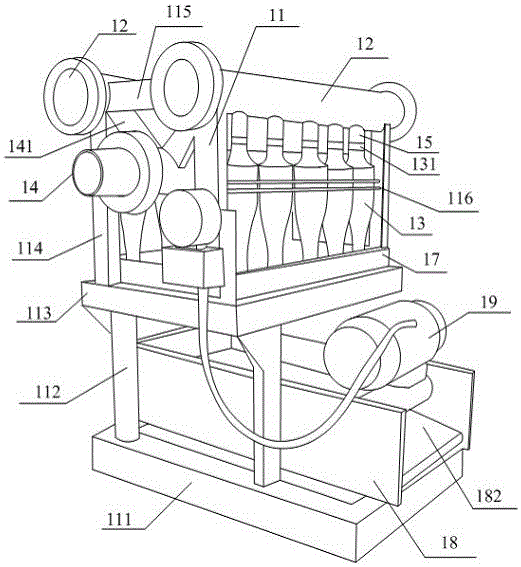
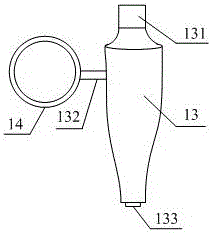
[0027] Such as figure 1 As shown, the sediment separator for oil drilling includes a frame 11, a slurry outlet pipe 12, a feed pipe 14, a cyclone desander 13, a temporary mud storage tank 17, and a vibrating screen 18.

[0028] Described frame 11 comprises: base 111, four first upright posts 112, fixed frame 113, four second upright posts 114, wherein, base 111 and fixed frame 113 are rectangular frame shape, and four first upright posts 112 stand respectively On the four corners of the base 111, the four corners of the fixed frame 113 are respectively fixed on the tops of the four first columns 112; the lower ends of the four second columns 114 are respectively fixed on the four corners of the fixed frame 113 .

[0029] The vibrating screen 18 is fixed on the base 111 .

[0030] The mud temporary storage tank 17 is welded in the fixed frame 113, that is, the outer wall of the mud temporary storage tank 17 is welded to the inner wall of the fixed frame 113, and the bottom of...

Embodiment 2

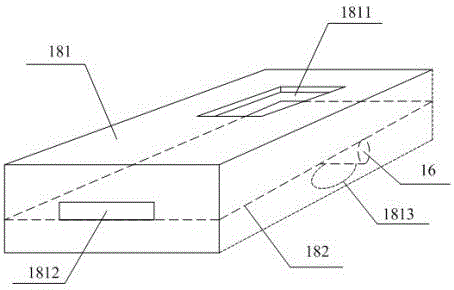
[0043] The difference between this embodiment and Embodiment 1 lies in the structure of the screen box 18 .

[0044] Such as image 3 As shown, in the present embodiment, screen box 18 is made of six panels of front, back, left, right, upper and lower, mud inlet 1811 is offered on the upper panel, silt outlet 1812 is offered on the front panel, and silt outlet 1812 is opened on the lower panel. The mud outlet 1813, the mud inlet 1811 is facing the sewage outlet of the mud temporary storage tank 17;

[0045] The sieve 182 is inclined to be placed high at the back and low at the front, and the lower end of the silt outlet 1812 on the front panel is flush with the sieve 182 to facilitate the flow of silt from the silt outlet 1812 .


PUM


Abstract

The invention discloses a mud-sand separator for petroleum drilling. The mud-sand separator comprises a machine frame, a mud temporary storage pool, two mud outlet pipes parallel to each other, a feeding pipe and a plurality of cyclone desanders, wherein the machine frame comprises a base in the shape of a rectangular frame, four first stand columns, a fixing frame and four second stand columns; a vibration sieve and the first stand columns are fixed to the base; the top ends of the four first stand columns and the lower ends of the four second stand columns are fixed to the four corners of the fixing frame; the mud temporary storage pool is welded in the fixing frame; a sewage outlet is formed in the bottom of the mud temporary storage pool; the mud outlet pipes are welded at the top ends of the second stand columns; a row of branch pipes are arranged on pipe bodies; the feeding pipe is fixed to the second stand columns, parallel to the mud outlet pipes and positioned above the mud temporary storage pool and below the mud outlet pipes; the cyclone desanders are mounted in two rows on two sides of the feeding pipe; and the top of each cyclone desander is connected with each branch pipe, the upper part of the cyclone desander is connected with the feeding pipe, and a sand outlet is formed in the bottom of the cyclone desander. According to the mud-sand separator, the cyclone desanders are adopted for mud separation simultaneously, so that the processing efficiency is high; the mud temporary storage pool is additionally arranged, so that empty opening is avoided and the energy is saved; and the mud-sand separator has the advantages of low cost and convenience for carrying.

Description

technical field [0001] The invention relates to the technical field of petroleum machinery, in particular to a sediment separator for petroleum drilling. Background technique [0002] During the entire drilling production process, the main pollutants are waste mud and cuttings, natural gas returned with drilling fluid circulation, H2S gas, mixture of oil gas and drilling fluid, etc. These pollutants are discharged the most, and the energy consumption of treatment , The material consumption is the largest, and the impact on the environment is also the largest. In the process of well control operations, such as overflow, well kick shut-in and well killing, etc., in order to avoid out-of-control blowout and fire on the well site, as well as possible personnel, equipment, wellbore unsafety and environmental pollution caused by it, pressure must be Blowout. According to the requirements, an outlet of the choke and kill manifold must be connected with a 100m blowout pipeline to ...

Claims


Application Information

Patent Timeline
IPC IPC(8): E21B21/06
CPCE21B21/065
Inventor 贺昶明
Owner CHENGDU DAMO PETROLEUM MACHINERY GRP
Why Eureka
Try Eureka