Pressure Balance Valve Common Rail Injector

A common rail injector and balancing valve technology, which is applied to machines/engines, fuel injection devices, engine components, etc., can solve the problems of reducing the area, increasing the multiple injection capability, affecting the injection rate of the injector, and achieving Increased fuel flow area, optimized fuel injection rate, accurate and reliable action

Inactive Publication Date: 2018-05-18
龙口龙泵柴油喷射高科有限公司
View PDF6 Cites 0 Cited by
  • Summary
  • Abstract
  • Description
  • Claims
  • Application Information

AI Technical Summary

Problems solved by technology

[0004] The existing high-pressure common rail electronically controlled fuel injector adopts a ball valve sealing structure, and the ball valve sealing diameter is 802, which will restrain each other in increasing the system injection pressure P and increasing the multiple injection capacity, because in order to increase the system pressure P, due to P =F / S formula, when the spring force F is constant, the sealing diameter must be reduced; however, reducing the sealing diameter will cause the control fuel flow opening area to become smaller under the same lift condition, which will Affects the injection rate of the injector; in order to optimize the injection rate, it is necessary to increase the lift; increasing the lift will inhibit the multiple injection capability
Therefore, the high-pressure fuel injection system of the prior art cannot well solve the difficult problem of not only further improving the system injection pressure P, but also increasing the multiple injection capability.

Method used


Image

  • Pressure Balance Valve Common Rail Injector
  • Pressure Balance Valve Common Rail Injector
  • Pressure Balance Valve Common Rail Injector

Examples


Embodiment Construction

[0032] In order to better understand the present invention, the implementation manners of the present invention will be explained in detail below in conjunction with the accompanying drawings.

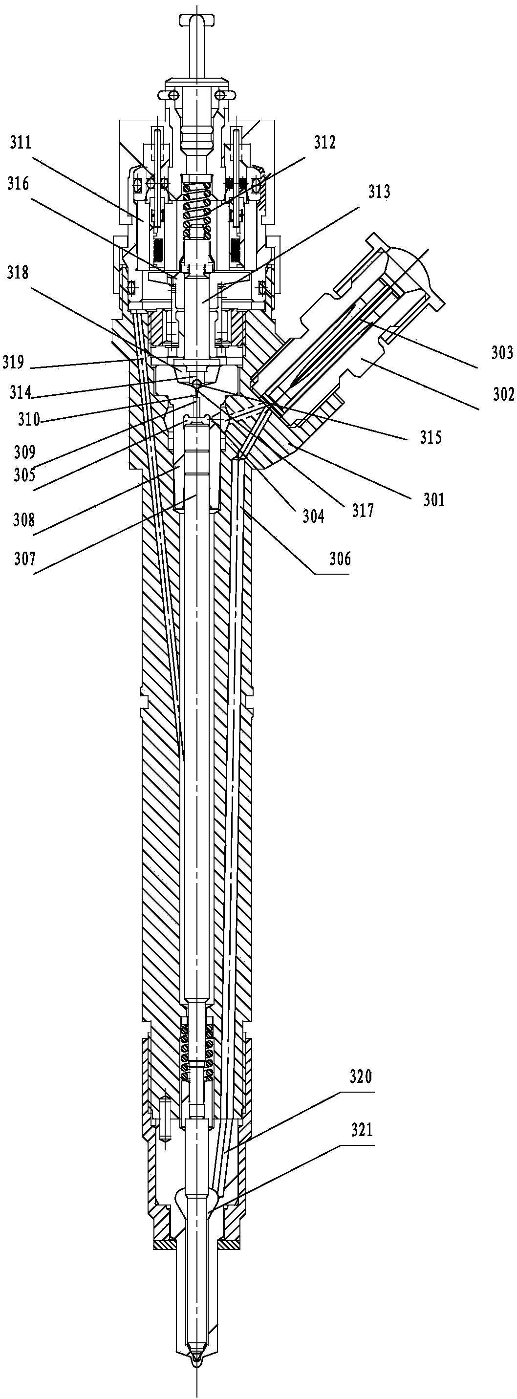
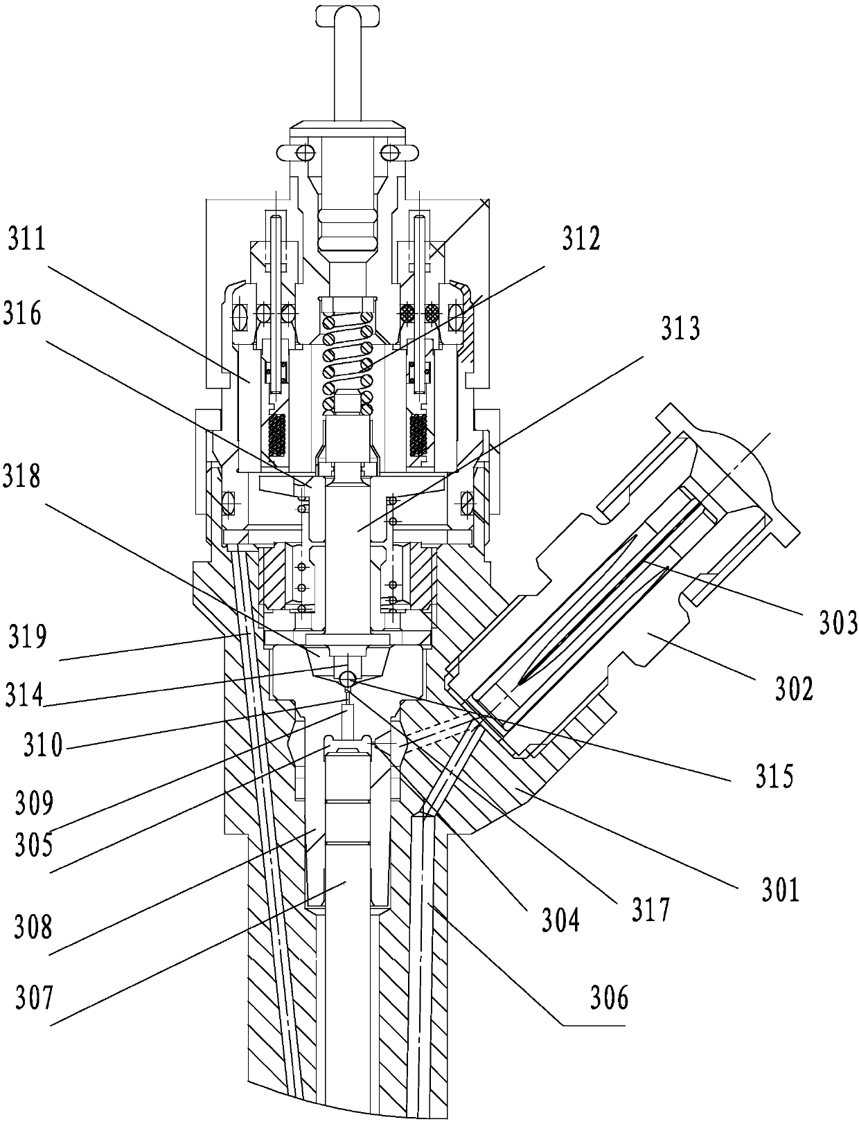
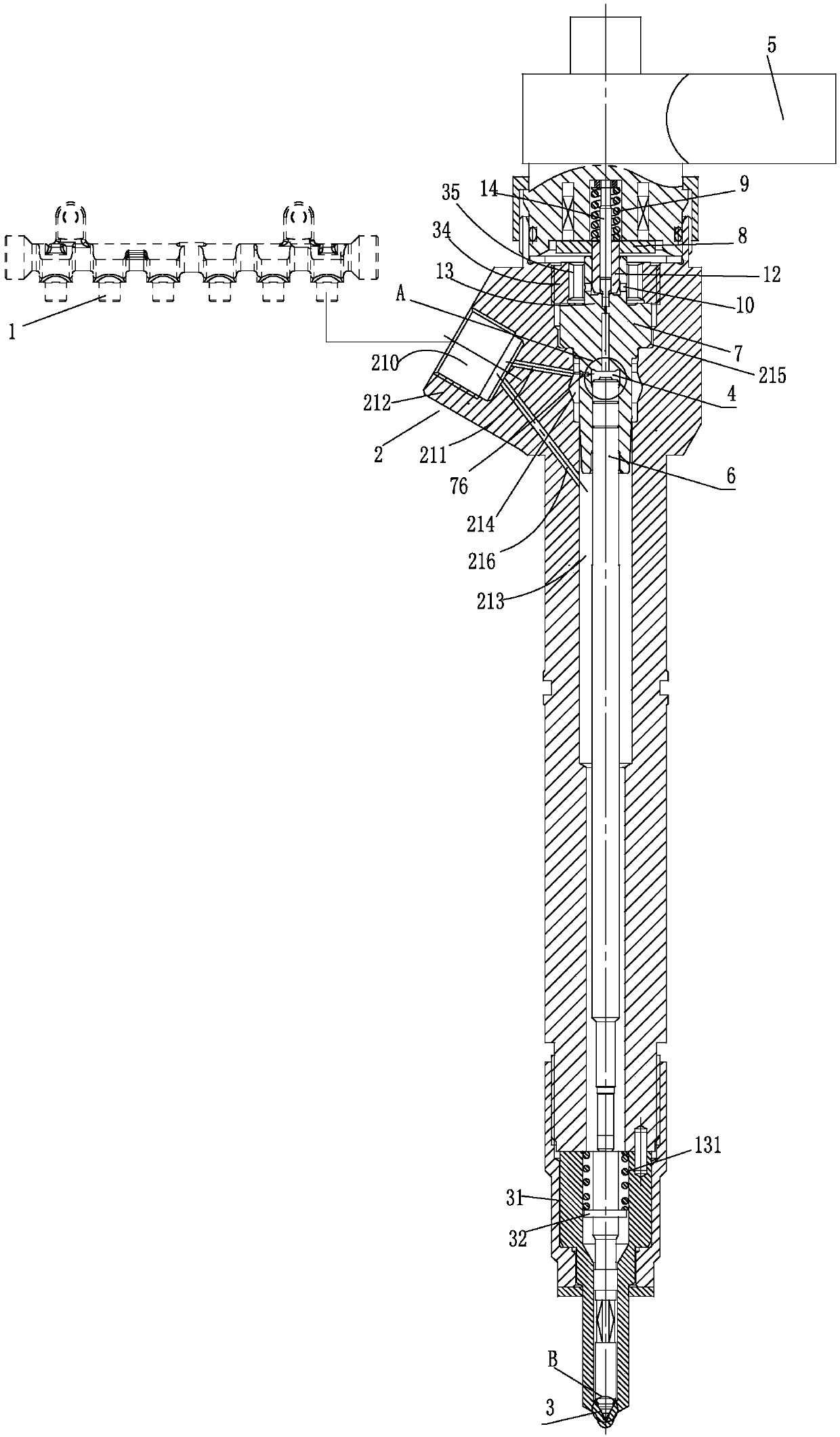
[0033] Such as Figure 3 to Figure 8 , Figure 10As shown, a pressure balance valve type common rail fuel injector includes a fuel injector body 2, a piston rod 6, a nozzle coupling, a pressure balance valve coupling, and a solenoid valve assembly. The upper part of the fuel injector body 2 is connected to the solenoid The lower part of the valve assembly is connected, the lower part of the pressure balance valve couple is connected with the upper part of the injector body 2, the lower part of the fuel injector body 2 is connected with the nozzle coupler, the nozzle coupler includes a needle valve 3, and the injector body 2 is axially In the center, there is a stepped cavity whose diameter decreases successively from top to bottom. The stepped cavity is formed by connecting and combin...


PUM


Abstract

The invention discloses a pressure-balanced valve type common-rail fuel injector which comprises a fuel injector body, a piston rod, fuel nozzle matching parts, pressure-balanced valve matching parts and an electromagnetic valve assembly.The fuel injector body is connected with the electromagnetic valve assembly, the pressure-balanced valve matching parts are connected with the fuel injector body, and the fuel injector body is connected with the fuel nozzle matching parts.The fuel nozzle matching parts comprise a needling valve, a step-shaped cavity is formed in the axial center of the fuel injector body, a sealing cavity is formed between the pressure-balanced valve matching parts and the piston rod, a protrusion is arranged on one side of the fuel injector body and provided with an inclined first fuel inlet hole of the fuel injector body, and a second fuel inlet hole of the fuel injector body is formed in the lower side of the first fuel inlet hole and is communicated with a fuel storage cavity in the lower portions of the pressure-balanced valve matching parts.The fuel injector body is connected with a high-pressure rail pipe, a fuel injector body fuel inlet is communicated with an upper portion inner hole, the upper portion inner hole is connected with a sealing cavity through a throttling hole, and a valve seat installation hole is formed in the upper portion of the upper portion inner hole and matched with the pressure-balanced valve matching parts.The diameter of the sealing surface on the upper portion of the piston rod is larger than the diameter of the intersecting line of the needle valve.

Description

technical field [0001] The invention relates to a fuel injection system used in an automobile internal combustion engine, in particular to a pressure balance valve type common rail fuel injector. Background technique [0002] Today, no matter from the goal of "National Thirteenth Five-Year Plan"---energy saving and emission reduction, or from the key goal of "Made in China 2025" (breaking through the injection pressure of diesel engines for key parts manufacturing to reach 2000bar), the high-pressure common rail fuel injection The system performance puts forward higher requirements. Only by further increasing the system injection pressure P and increasing the multiple injection capability can the stringent emission regulations be met. [0003] Existing high-pressure common rail electronically controlled injectors, such as figure 1 , figure 2 , Figure 9 In the structure shown, after the high-pressure fuel passes through the slit filter element 303 in the high-pressure co...

Claims


Application Information

Patent Timeline
Patent Type & Authority Patents(China)
IPC IPC(8): F02M47/02F02M51/06F02M61/10
CPCF02M47/02F02M51/061F02M61/10
Inventor 孙平郭兴王丽芬张海涛贾玉杰刘本学
Owner 龙口龙泵柴油喷射高科有限公司
Why Eureka
Try Eureka