A gas cycle waste incinerator

A technology of waste combustion and gas circulation, applied in the combustion method, combustion type, lighting and heating equipment, etc., can solve the problems of air pollution, land erosion, slow speed of combustible gas, etc., to ensure the processing temperature, improve the heat utilization rate, The effect of improving combustion efficiency

Inactive Publication Date: 2017-12-26
SINOBIOWAY BIOENVIRONMENT CO LTD
View PDF8 Cites 0 Cited by
  • Summary
  • Abstract
  • Description
  • Claims
  • Application Information

AI Technical Summary

Problems solved by technology

It is usually disposed of in landfill, causing waste to erode a large amount of land
The incineration method can maximize the effective treatment of domestic waste and occupy the least land resources. However, if the incineration tail gas is discharged directly without treatment, it will cause serious air pollution.
In the existing waste treatment technology, pyrolysis gasification is the main method, but due to the poor air permeability of the waste in the furnace, the combustible gas produced by high-temperature pyrolysis of waste escapes slowly from the waste heap.

Method used


Image

  • A gas cycle waste incinerator

Examples


Embodiment Construction

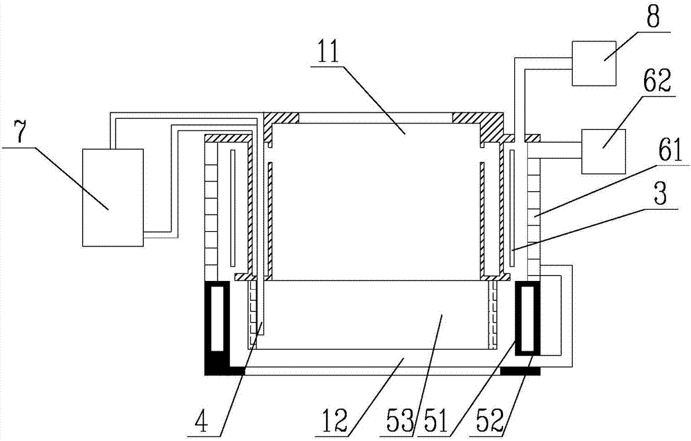
[0018] Such as figure 1 as shown, figure 1 It is a schematic structural diagram of a gas cycle garbage incineration device proposed by the present invention.

[0019] refer to figure 1 , a kind of gas cycle garbage burning equipment proposed by the present invention, comprising: a combustion furnace, an air intake device, a circulating gas cooling device 7, and an exhaust gas treatment device 8;

[0020] The inside of the combustion furnace has a furnace chamber for burning garbage. The top of the furnace chamber is provided with a garbage inlet, the lower part of the furnace chamber is provided with an air inlet, an air outlet, and an exhaust gas outlet. The bottom of the furnace chamber is provided with a slagging port. Comprising an upper furnace body 11 and a lower furnace body 12;

[0021] The outer periphery of the furnace wall of the upper furnace body 11 is provided with a peripheral wall, and a first cooling cavity is formed between the peripheral wall and the furn...


PUM


Abstract

The invention discloses waste combustion equipment capable of achieving efficient gas circulation. Household waste is put into a furnace cavity of a combustion furnace from the top, and air is supplied into the furnace cavity from the bottom, so that the waste is combusted upwards from the bottom; and circulating gas at the top of the furnace cavity returns to the bottom of the furnace cavity for combustion supporting after moisture in the circulating gas is removed, and final tail gas generated during waste combustion is exhausted after being sufficiently combusted on the lower portion of the furnace cavity, so that the temperature in the furnace cavity is decreased gradually from bottom to top. Through the optically-designed waste combustion equipment capable of achieving efficient gas circulation, an annular cooling cavity arranged outside a furnace body can effectively cool the lower portion of the furnace body; meanwhile, in one aspect, air enters the furnace cavity after being preheated when flowing through the periphery of the upper portion of the furnace body, and thus the temperature in the furnace cavity is guaranteed; in another aspect, the tail gas is exhausted after being cooled through a cooling cavity, so that subsequent tail gas treatment is facilitated; and in another aspect, inlet circulating gas is preheated through outlet circulating gas, so that the heat utilization rate is greatly increased, the treatment temperature in the furnace cavity is guaranteed, high-temperature gas is effectively cooled before being exhausted, and the combustion efficiency in the furnace cavity is effectively improved.

Description

technical field [0001] The invention relates to the technical field of garbage treatment, in particular to a gas cycle garbage burning equipment. Background technique [0002] In recent years, with the improvement of people's living standards, the generation of municipal solid waste has increased rapidly, and the stock of waste accumulation over the years has been huge. It is usually disposed of by landfill, causing waste to erode a large amount of land. The incineration method can maximize the effective treatment of domestic waste and occupy the least land resources. However, if the incineration tail gas is discharged directly without treatment, it will cause serious air pollution. In the existing waste treatment technology, pyrolysis gasification is the main method. However, due to the poor air permeability of waste in the furnace, the combustible gas generated by high-temperature pyrolysis of waste escapes slowly from the waste heap. Therefore, how to clean up domestic ...

Claims


Application Information

Patent Timeline
Patent Type & Authority Patents(China)
IPC IPC(8): F23G5/00F23G5/46
CPCF23G5/00F23G5/46F23G2206/10
Inventor 李启仁曹文波明永刚舒志强
Owner SINOBIOWAY BIOENVIRONMENT CO LTD
Why Eureka
Try Eureka