
Indoor positioning method adopting visible light and inert composition

An indoor positioning and inertial combination technology, applied in surveying and navigation, measuring devices, instruments, etc., can solve problems such as difficult to ensure positioning continuity, achieve continuous independent high-precision indoor positioning, easy engineering implementation, and ensure the quality of positioning

Inactive Publication Date: 2016-06-15
NO 20 RES INST OF CHINA ELECTRONICS TECH GRP
View PDF3 Cites 27 Cited by
  • Summary
  • Abstract
  • Description
  • Claims
  • Application Information

AI Technical Summary

Problems solved by technology

However, in order to ensure positioning performance, it is necessary to consider the distribution of indoor SNR to avoid blind spots and shadows, especially in the case of cross-room, LED failure, etc., it is difficult to ensure the continuity of positioning
The current solution is to alleviate the existing problems by improving the light source, eliminating inter-symbol interference, optimizing LED layout, etc., which cannot completely solve the problem

Method used


Image

  • Indoor positioning method adopting visible light and inert composition

Examples


Embodiment Construction

[0015] The present invention will be further described below in conjunction with the accompanying drawings and embodiments, and the present invention includes but not limited to the following embodiments.

[0016] The present invention comprises the following steps:

[0017] Step 1: Analyze the relationship between the received optical signal intensity and the coverage area in the laboratory to calibrate the light intensity threshold. Use the bit error rate to distinguish the light intensity coverage area and coverage blind area to ensure that the communication bit error rate of the LED coverage area is less than 10 -9 .

[0018] Specifically, set up an LED optical communication link, and send not less than 10 10 bytes of binary test data, and receive this set of data at the receiving end to test the bit error rate of the link. The number of tests should not be less than 3 times. When the bit error rate is less than 10 -9 , it is defined as the coverage area of ​​LED light...


PUM


Abstract

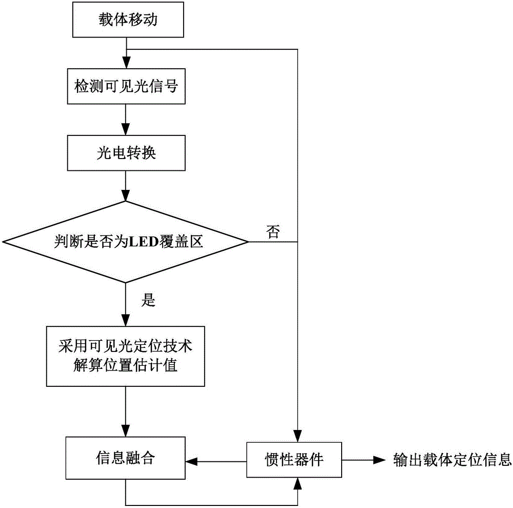
The invention provides an indoor positioning method adopting visible light and inert composition. A mobile carrier can detect a visible light signal in a process of moving in a room. The indoor positioning method comprises the following steps: judging whether the mobile carrier is positioned in a visible light strong coverage region according to a light intensity threshold value; if a light intensity value is less than the light intensity threshold value, directly taking a position estimation value acquired by an inert device as carrier positioning information; if the light intensity value is greater than or equal o the light intensity threshold value, calculating the position estimation value according to the visible light signal, subtracting the position estimation value acquired by the inert device from the position estimation value calculated according to the visible light signal, and performing Kalman filtering on an obtained difference value to obtain a drift error of the inert device, wherein the drift error is used for correcting the inert device, and the corrected position estimation value of the inert device is used as the carrier positioning information. According to the indoor positioning method, the influence caused by a cover blind area and a shadow in a visible light positioning process can be effectively avoided, and the shortcoming that the error of the inert device is accumulated along the time is overcome; continuous automatic high-precision indoor positioning is realized.

Description

technical field [0001] The invention relates to an indoor positioning method. Background technique [0002] The existing positioning systems mainly include satellite navigation system (GNSS), inertial navigation system and radio navigation system. Indoors, the GPS signal is severely blocked and is not applicable. Inertial devices have the characteristics of strong autonomy and high short-term accuracy, but their errors are easy to accumulate over time. Using them alone cannot meet the needs of indoor high-precision positioning, and often need to be used in combination with other high-precision positioning methods. Indoor positioning based on radio waves includes Wifi, Bluetooth, WLAN, etc., which have high positioning accuracy, but are easily affected by electromagnetic interference. When shared by multiple users, the positioning quality is not good, and they are not suitable for use in electromagnetic sensitive environments. [0003] In recent years, the indoor positionin...

Claims


Application Information

Patent Timeline
Patent Type & Authority Applications(China)
IPC IPC(8): G01C21/16G01C21/20
CPCG01C21/206G01C21/165
Inventor 武云云魏伟
Owner NO 20 RES INST OF CHINA ELECTRONICS TECH GRP
Learn More