Contactless power supply coupling device for magnetic-levitation train and magnetic-levitation train

A non-contact power supply, maglev train technology, applied in electric traction, electric vehicles, electric energy management and other directions, can solve the problems such as the inability to realize the movement of the magnetic flux relative to the generator coil, the inability of the permanent magnet to slot and lay the coil, and the unworkable linear power generation scheme. , to achieve the effect of reducing the weight of the car body and maintenance management, facilitating maintenance and saving space

Inactive Publication Date: 2016-06-22
NAT UNIV OF DEFENSE TECH
View PDF5 Cites 9 Cited by
  • Summary
  • Abstract
  • Description
  • Claims
  • Application Information

AI Technical Summary

Problems solved by technology

The suspension of the medium-speed vehicle is separated from the traction system. The main structure of the traction system is a permanent magnet array and a long stator. It is impossible to slot and lay coils on the permanent magnet. Moreover, the long stator of the medium-speed vehicle is potted with resin and does not contain materials such as silicon steel sheets. No cogging and consequently no ability to induce flux relative to coil motion
In the suspension system, it is also impossible to realize the movement of the magnetic flux relative to the generator coil, so the linear power generation scheme is not feasible

Method used


Image

  • Contactless power supply coupling device for magnetic-levitation train and magnetic-levitation train
  • Contactless power supply coupling device for magnetic-levitation train and magnetic-levitation train
  • Contactless power supply coupling device for magnetic-levitation train and magnetic-levitation train

Examples


Embodiment Construction

[0024] In order to enable those skilled in the art to better understand the technical solutions of the present invention, the present invention will be further described in detail below in conjunction with the accompanying drawings.

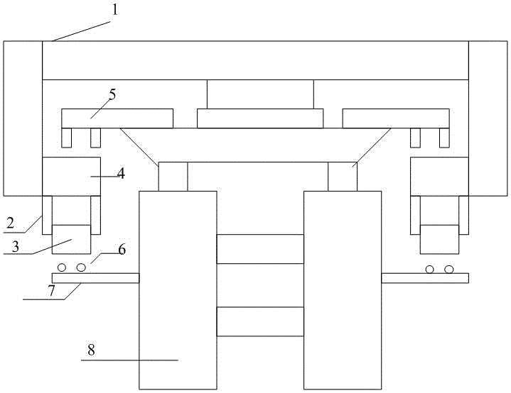
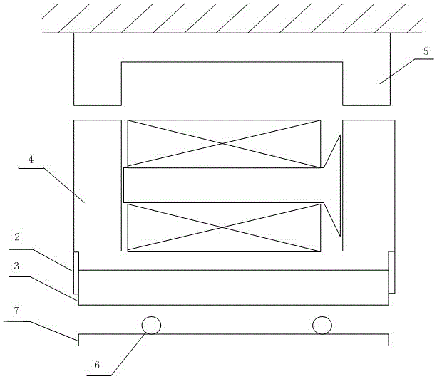
[0025] see figure 1 and figure 2 , figure 1 It is a schematic diagram of the installation of a non-contact power supply coupling device for a maglev train provided by the present invention, figure 2 for figure 1 left view of .

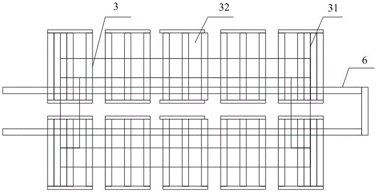
[0026] The non-contact power supply coupling device for maglev trains includes a transmitting end 6 and a receiving end 3, wherein: the receiving end 3 is installed under the suspension electromagnet 4 on one side of the train through the receiving end bracket 2 parallel to the ground, and the receiving end 3 is formed by a multi-turn rectangular coil It is formed in series in a spiral shape, and the two ends of the coil are connected with the lower-level power equipment, and the high-frequency current is converted ...


PUM


Abstract

The invention discloses a contactless power supply coupling device for a magnetic-levitation train and the magnetic-levitation train. The contactless power supply coupling device for the magnetic-levitation train comprises an emitting end and a receiving end, wherein the receiving end is formed by connecting multiple turns of rectangular coils spirally in series; the receiving end is arranged below a levitation electric magnet on one side of the train through a receiving end support which is parallel to the ground; the emitting end is formed by two parallel long straight cables; the initial ends of the two long straight cables are connected with the output end of an inverter; the tail ends of the two long straight cables are connected; the emitting end is arranged on the outer side of a guide rail through an emitting end support in a manner of being parallel to the ground; the guide rail is located on the same side of the train as the levitation electric magnet for assembling the receiving end; and the emitting end is right below the receiving end. According to the contactless power supply coupling device, a train body is not changed in large scale, and power supply for the intermediate speed magnetic-levitation train is realized. Information about a clearance between the emitting end and the receiving end is obtained through arrangement of existing levitation sensors, and arrangement of special sensor components is avoided, so that cost is effectively reduced, and the dead-weight of the train body and maintenance management work load are lowered.

Description

technical field [0001] The invention relates to the field of medium-speed maglev trains, in particular to a non-contact power supply coupling device for maglev trains. The present invention also relates to a maglev train provided with the above-mentioned non-contact power supply coupling device. Background technique [0002] The traditional contact power supply method in the field of rail transit has problems such as exposed wires, electric sparks, friction loss, and the power supply process is easily affected by the external environment, which seriously affects the safe operation of vehicles. As a product of high technology, the maglev train adopts a non-contact power supply scheme. At present, the well-developed maglev trains are Germany's constant conduction electromagnetic maglev train and Japan's superconducting electric levitation train. The on-board energy of high-speed maglev vehicles is usually generated by means of a linear generator, by installing a generator coi...

Claims


Application Information

Patent Timeline
Patent Type & Authority Applications(China)
IPC IPC(8): B60L13/04
CPCB60L13/04Y02T10/72
Inventor 杨鑫龙志强文艳晖黄号凯范成鑫侯圣杰矫岩峻林志凯
Owner NAT UNIV OF DEFENSE TECH
Why Eureka
Try Eureka