Splicing structure, splicing method and splicing box body

A box body and reinforcement structure technology, which is applied in the field of water tank box body production in sewage treatment, can solve the problems of large space occupation, low production efficiency, and high cost, and achieve the effects of reduced space occupation, low production cost, and simple production

Active Publication Date: 2016-06-22
BIOLOGICAL TECH INST OF FUJIAN ACADEMY OF AGRI SCI +1
View PDF6 Cites 11 Cited by
  • Summary
  • Abstract
  • Description
  • Claims
  • Application Information

AI Technical Summary

Problems solved by technology

[0004] For this reason, it is necessary to provide a splicing structure, a splicing method, and a splicing box body to solve the problems of complex processing of the water tank body,

Method used


Image

  • Splicing structure, splicing method and splicing box body
  • Splicing structure, splicing method and splicing box body
  • Splicing structure, splicing method and splicing box body

Examples


Embodiment Construction

[0060] In order to describe in detail the technical content, structural features, achieved purpose and effect of the technical solution, the following in conjunction with specific embodiments and with the accompanying Figure 1a-Figure 6b Explain in detail.

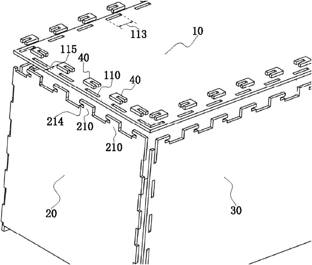
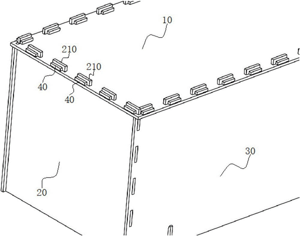
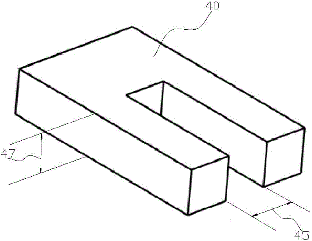
[0061] see Figure 1a An exploded schematic view of a splicing structure provided by the inventor is shown, the splicing structure includes a first side plate 10, a second side plate 20, and a fastener 40; the splicing structure is a part of the box, and the first side plate and the second The two side panels are combined and fixed by the splicing structure as shown in the figure, so that the first side panel and the second side panel are L-shaped to each other.

[0062]The first side plate 10 is provided with at least one opening 110 close to at least one side thereof, and the opening 110 penetrates both sides of the first side plate; the size of the opening is not limited, and the first side plate 10 One side may have ...


PUM


Abstract

The inventor provides a splicing structure, a splicing method and a splicing box body. The problems that the injection molding cost of the box body is high and the box body molded by injection occupies a large space and is inconvenient to transport and store are solved. The inventor relates to the splicing structure, in particular to a splicing structure between plates. The splicing structure comprises a first side plate, a second side plate and a fastener, wherein at least one hole is formed in the position, close to at least one side edge, of the first side plate, and the hole penetrates through the two sides of the first side plate; at least one bulge is arranged in the position, close to at least one side edge, of the second side plate; the bulge is opposite to the hole, and the bulge can penetrate through the hole and can be embedded in the hole; an open slot is formed in at least one side of the bulge; and after the bulge penetrates through the hole, the fastener is embedded in the open slot so as to assemble and fix the first side plate and the second side plate.

Description

technical field [0001] The invention relates to a splicing structure, in particular to the fabrication of a splicing structure between plates, a liquid container, a breeding container, and a water tank in sewage treatment. Background technique [0002] The water tank casings used in some existing water treatment products are usually formed by cutting, chamfering, splicing and welding plastic plates such as PVC boards according to actual needs. The plates cut into rectangles need to be temporarily fixed with clamps during the splicing process, and then the joints of the two plates are welded inside and outside with PVC welding rods under the heating of hot air, so as to achieve the purpose of forming the water tank and preventing the water tank from leaking , and the weld seam of the common welded water tank body is not protected by external force, the pressure it can withstand is limited, and problems such as water leakage and cracking often occur. [0003] In addition, exi...

Claims


Application Information

Patent Timeline
IPC IPC(8): B65D6/24B65D6/34B65D81/38A01K63/00
CPCA01K63/003B65D11/1873B65D11/26B65D13/02B65D81/38
Inventor 柯翎
Owner BIOLOGICAL TECH INST OF FUJIAN ACADEMY OF AGRI SCI
Why Eureka
Try Eureka