
Continuous electrolytic cell for potassium ferrate

A technology of potassium ferrate and electrolyzer, applied in electrolysis process, electrolysis components, cells, etc., can solve the problems of high reaction temperature, affecting production efficiency, low utilization rate, etc., achieve high electrolysis efficiency, improve production efficiency, and scientific design Effect

Inactive Publication Date: 2016-06-22
HENAN VOCATIONAL COLLEGE OF APPLIED TECH
View PDF5 Cites 3 Cited by
  • Summary
  • Abstract
  • Description
  • Claims
  • Application Information

AI Technical Summary

Problems solved by technology

The high-temperature melting method is an early preparation method, which is relatively mature, but the reaction temperature is high, the product purity is low, and the preparation process has the risk of explosion, so it is rarely used now; the hypochlorite oxidation method is a wet preparation method, and the process is complicated. Unstable, its utilization rate is low, and the yield of potassium ferrate is not high, the purity of the primary product is low, and the container is severely corroded; the electrolysis method is convenient and flexible to operate, requires less raw materials, and the product collection and processing are more convenient, which can be investigated There are many parameters, and the research space is large
[0004] However, in the production process of electrolysis, the anode sludge needs to be cleaned regularly. This process requires shutdown operation, and the cleaning time is too long, which seriously affects the efficiency of producing potassium ferrate.
[0005] In addition, the primary solid product of potassium ferrate needs to be discharged regularly, which will also affect production efficiency

Method used


Image

  • Continuous electrolytic cell for potassium ferrate

Examples


Embodiment Construction

[0026] The technical solutions of the present invention will be described in further detail below through specific implementation methods.

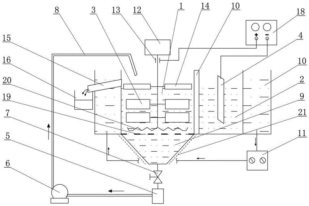
[0027] Such as figure 1 Shown, a kind of potassium ferrate continuous electrolyzer, it comprises electrolyzer and electrolysis electrode, described electrolyzer lower end communicates with sediment collection chamber 9, and described mud collection chamber 9 is connected with sediment bin 5 by valve 7, so The high position of the sedimentation bin 5 communicates with the electrolytic cell through a return pipe 8 , and the return pipe 8 is provided with return power by a circulation pump 6 .

[0028] This part realizes the automatic cleaning of the sludge. After the sludge has accumulated to a certain extent in the sludge collection chamber 9, the valve 7 is opened, and the sludge enters the sludge bin 5 to clarify the electrolyte. The clarified electrolyte plays a role in the circulating pump 6. Down flow back into the electrolytic cell ...


PUM


Abstract

The invention provides a continuous electrolytic cell for potassium ferrate. The continuous electrolytic cell for potassium ferrate comprises an electrolytic cell body and an electrolytic electrode. The lower end of the electrolytic cell body communicates with a silt collecting chamber which is connected with a silt bin through a valve; the high position of the silt bin communicates with the electrolytic cell body through a backflow pipe; backflow power is supplied to the backflow pipe by a circulating pump; the electrolytic cell body comprises an anode chamber, a cathode chamber, a diaphragm assembly and a temperature control device; a stirrer is vertically mounted in the anode chamber; an electric brush, helical blades and iron electrodes are sequentially arranged on a stirring shaft of the stirrer; a potassium ferrate discharge opening is formed in the upper side portion of the anode chamber; the helical blades are arranged corresponding to the potassium ferrate discharge opening; the electric brush is connected with the positive pole of a direct current power source; and the negative pole of the direct current power source is connected with a graphite electrode in the cathode chamber. The continuous electrolytic cell for potassium ferrate has the advantages of being scientific in design, capable of enabling electrolyte to be recycled and automatically collecting potassium ferrate coarse materials, capable of achieving continuous uninterrupted production and high in electrolytic efficiency.

Description

technical field [0001] The invention relates to a chemical preparation equipment, in particular to a continuous electrolytic cell for potassium ferrate. Background technique [0002] With the development of social economy, the expansion of urban scale and the continuous growth of population, the shortage of water resources and the treatment of wastewater have become one of the most important problems in society. In emergencies such as earthquakes, drinking water safety issues also need to be addressed. The best solution to improve water resources and enhance the safety level of drinking water is to add water treatment agents. Potassium ferrate, a new high-efficiency and multi-functional green water treatment agent, is an ideal product. Compared with chlorine and other drinking water disinfectants, its advantages are outstanding: High safety, versatility, wide pH range, high efficiency, convenience. In addition, the potential application of potassium ferrate in the electron...

Claims


Application Information

Patent Timeline
Patent Type & Authority Applications(China)
IPC IPC(8): C25B1/14C25B9/00C25B15/08
CPCC25B1/14C25B9/00C25B15/08
Inventor 赵扬蔡庄红贺素姣付永付大勇朱冰甄超英崔晨张海英
Owner HENAN VOCATIONAL COLLEGE OF APPLIED TECH
Learn More