
Aircraft carbon-carbon composite brake disc and manufacturing method thereof

A carbon composite material and brake disc technology, applied in the direction of brake disc, mechanical equipment, brake type, etc., can solve the problems of limited application and development of carbon cloth lamination method, easy delamination, peeling, low material utilization rate, etc. Achieve the effect of favorable thermal protection, long service life and high utilization rate of raw materials

Active Publication Date: 2018-08-07
XIAN AVIATION BRAKE TECH
View PDF10 Cites 2 Cited by
  • Summary
  • Abstract
  • Description
  • Claims
  • Application Information

AI Technical Summary

Problems solved by technology

Since the carbon brake disc obtained by lamination of carbon cloth is a laminate structure, the shortcoming of this carbon brake disc is mainly the poor thermal conductivity in the direction perpendicular to the friction surface (that is, along the central axis of the carbon brake disc, abbreviated as Z direction). , the thermal conductivity in the direction parallel to the friction surface (that is, the radial direction) is much higher than the Z thermal conductivity, and it is easy to delaminate and peel off during use.
In addition, the remaining large pieces of round cloth are discarded, and the material utilization rate is low
Therefore, the application and development of carbon cloth lamination method is limited

Method used


Image

  • Aircraft carbon-carbon composite brake disc and manufacturing method thereof
  • Aircraft carbon-carbon composite brake disc and manufacturing method thereof

Examples


Embodiment 1

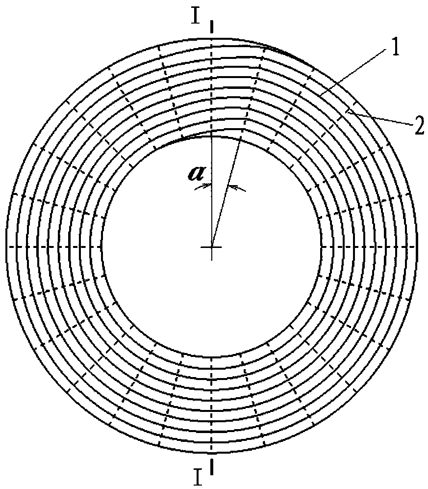
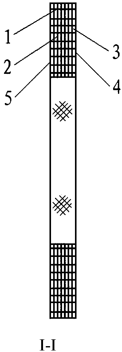
[0030] The invention relates to a carbon-carbon composite material brake disk for aircraft wheels. The carbon brake disc is composed of continuous circumferentially wound polyacrylonitrile carbon fiber cloth 1 , polyacrylonitrile carbon fiber wires 2 radially penetrating the polyacrylonitrile carbon fiber cloth layer and a carbon matrix 7 . The polyacrylonitrile carbon fiber wires 2 are evenly distributed along the circumferential direction and the thickness direction. The carbon brake disc has two sides both of which participate in friction, forming a first friction surface 5 and a second friction surface 6 . The first friction surface 5 and the second friction surface 6 of the carbon brake disc include side ends of a plurality of carbon fiber cloth roll layers and a carbon matrix 3 . As the surface wears, the carbon fiber threads that connect the carbon fiber cloth roll layers also become components of the friction surface. The carbonaceous matrix is ​​resinous carbon obta...

Embodiment 2

[0048] The invention relates to a carbon-carbon composite material brake disk for aircraft wheels. The carbon brake disc is composed of continuous circumferentially wound polyacrylonitrile carbon fiber cloth and polyacrylonitrile carbon fiber felt 3, and the polyacrylonitrile carbon fiber line 2 radially passing through the polyacrylonitrile carbon fiber cloth and polyacrylonitrile carbon fiber felt layer The reinforcement is composed of a carbonaceous matrix. The polyacrylonitrile carbon fiber lines 2 are evenly distributed along the circumferential direction and the axial direction of the carbon brake disc. The friction surface of the carbon brake disc includes a plurality of carbon fiber cloths, the side ends of the felt roll layer and the carbon matrix, and the carbon brake disc composed of the plurality of carbon fiber cloths, the side ends of the felt roll layer and the carbon matrix The two sides form the first friction surface 5 and the second friction surface 6 of th...

Embodiment 3

[0066] This embodiment is a carbon-carbon composite material brake disc for an aircraft wheel. The carbon brake disc is composed of continuous circumferentially wound polyacrylonitrile carbon fiber mat 4 and reinforcements of polyacrylonitrile carbon fiber wires 2 that radially penetrate the polyacrylonitrile carbon fiber mat layer and are composited with a carbon matrix. The polyacrylonitrile carbon fiber wires 2 are evenly distributed along the circumferential direction and the thickness direction. The friction surface of the carbon brake disc includes side ends of multiple carbon fiber felt roll layers and a carbon matrix. As the surface wears, the carbon fiber threads that connect the carbon fiber felt rolls can also become components of the friction surface. The carbonaceous matrix is ​​deposited carbon.

[0067] The aircraft carbon-carbon composite brake disc has two friction surfaces, which are the first friction surface 4 and the second friction surface 5 respectivel...


PUM

PropertyMeasurementUnit
pore sizeaaaaaaaaaa
distanceaaaaaaaaaa
diameteraaaaaaaaaa

Abstract

The invention relates to an aircraft carbon-carbon composite material brake disc and a manufacturing method thereof. The aircraft carbon-carbon composite material brake disc is formed in manners that composite layers formed by carbon fiber cloth or polyacrylonitrile carbon fiber felts or stacking of the carbon fiber cloth and the polyacrylonitrile carbon fiber felts are continuously and circumferentially wound, and carbon fiber lines penetrating winding layers in the radial direction and a carbon matrix are compounded; and through the thickening technology and the follow-up treatment, the aircraft carbon-carbon composite material brake disc is obtained. A first friction surface and a second friction surface are formed on the two side faces of the carbon brake disc, and the carbon fiber lines of the winding layers of the carbon fiber cloth also become components of the friction surfaces along with surface abrasion. The fiber orientation of the carbon brake disc can be parallel to the friction surfaces or vertical to the friction surfaces, or a certain angle is formed between the fiber orientation of the carbon brake disc and the friction surfaces, and therefore the frictional wear performance is better stabilized and improved. The state is completely different from the state when the carbon cloth plane lamination carbon disc fibers are parallel to the friction surfaces, and the aircraft carbon-carbon composite material brake disc has the beneficial effects that the service life is longer, and the combination property of the carbon brake disc is better.

Description

technical field [0001] The invention relates to the field of aircraft wheel brake devices, in particular to a carbon-carbon composite material brake disc for an aircraft wheel brake device and a manufacturing method thereof. Background technique [0002] Aircraft carbon brakes refer to the brake disc parts that make up the brake heat reservoir, which are made of carbon-carbon composite materials. Compared with steel brakes, they have the advantages of light weight, wear resistance, high specific heat, and high temperature non-bonding. It has significantly improved the technical performance, reliability, safety and economy of the aircraft, so it has been widely used in modern aircraft. Carbon-carbon composite brake discs for aircraft wheel brakes are often referred to as aircraft carbon brake discs, carbon brake discs or carbon discs. A carbon brake disc of a carbon brake device includes a pressure disc, several moving discs, several static discs and a pressure disc. A numb...

Claims


Application Information

Patent Timeline
Patent Type & Authority Patents(China)
IPC IPC(8): F16D65/12B29C70/44C04B35/83
CPCB29C70/443C04B35/83C04B2235/48C04B2235/5248C04B2235/5256C04B2235/614C04B2235/616F16D65/126F16D2200/0052F16D2200/0065F16D2200/0091F16D2250/0046
Inventor 何永乐
Owner XIAN AVIATION BRAKE TECH
Learn More