Synchronous rectifier control circuit, method and switching power supply provided with same
A synchronous rectification and control circuit technology, which is applied in the direction of electrical components, output power conversion devices, AC power input conversion to DC power output, etc., can solve problems such as back-feeding current, improve reliability and prevent damage Effect
- Summary
- Abstract
- Description
- Claims
- Application Information
AI Technical Summary
Problems solved by technology
Method used
Image

Examples
Embodiment 1
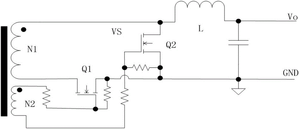
[0039] Figure 4 It shows the synchronous rectification drive control circuit of Embodiment 1 of the present invention, including a transformer winding self-driven synchronous rectification circuit 1, an output variation voltage sampling circuit 2 and a drive control circuit 3; the transformer winding self-driven synchronous rectification circuit 1 includes two synchronous rectification circuits MOS tubes Q1 and Q2; the input end of the output change voltage sampling circuit 2 is connected to the output voltage Vo of the switching power supply, and the output end is connected to the input end of the drive control circuit; the two output ends of the drive control circuit are respectively connected to two synchronous rectification MOS tubes Gates of Q1 and Q2;
[0040] Compared with the prior art, the transformer winding self-driven synchronous rectification circuit also includes a drive capacitor C1 and a drive capacitor C2; one end of the drive capacitor C1 is connected to one...
Embodiment 2
[0049] Figure 6 It shows the synchronous rectification driving control circuit of the second embodiment of the present invention, the difference from the first embodiment is:
[0050] The output change voltage sampling circuit adds a discharge diode D1, and its connection relationship is that the cathode of the discharge diode D1 is connected to the connection point of the sampling capacitor C3 and the current limiting resistor R1, and the anode of the discharge diode D1 is connected to the secondary reference point GND of the switching power supply.
[0051] The working principle of this embodiment is analyzed as follows:
[0052] Such as Figure 4 In the circuit of Embodiment 1 shown, when the output voltage drops when the power is turned off, upper positive and lower negative voltages are generated on the sampling capacitor C3, and the voltage will be maintained for a short time after the power is turned off. During the re-starting process of the switching power supply, ...
Embodiment 3
[0054] Figure 7 It shows the synchronous rectification drive control circuit of the third embodiment of the present invention, the difference from the second embodiment is:
[0055] The current limiting resistor R1 of the output variation voltage sampling circuit is removed, and the sampling resistor R1 is connected in parallel at both ends of the discharge diode D1.
[0056] The triode Q3 of the driving control circuit is replaced by a MOS transistor Q3, the gate of the MOS transistor Q3 is the input terminal of the driving control circuit, the source of the MOS transistor Q3 is connected to the secondary reference point GND of the switching power supply, and the drain of the MOS transistor Q3 is connected to The cathodes of the isolation diode D2 and the isolation diode D3, and the anodes of the isolation diode D2 and the isolation diode D3 are the two output terminals of the drive control circuit.
[0057] The working principle of this embodiment is slightly different fro...
PUM
 Abstract
Description
Claims
Application Information
 - R&D
- Intellectual Property
- Life Sciences
- Materials
- Tech Scout
- Unparalleled Data Quality
- Higher Quality Content
- 60% Fewer Hallucinations
Browse by: Latest US Patents, China's latest patents, Technical Efficacy Thesaurus, Application Domain, Technology Topic, Popular Technical Reports.
© 2025 PatSnap. All rights reserved.Legal|Privacy policy|Modern Slavery Act Transparency Statement|Sitemap|About US| Contact US: help@patsnap.com