Filtering assembly and dust collector with same

A filter assembly and box technology, applied in vacuum cleaners, suction filters, household appliances, etc., can solve the problems of uneven flow cross-sectional area change, large particle garbage blocking the air intake pipe, and high bubble collapse noise. For gas-liquid separation, improve filtration effect, reduce impact effect

Inactive Publication Date: 2016-06-29
MIDEA GRP CO LTD
View PDF6 Cites 6 Cited by
  • Summary
  • Abstract
  • Description
  • Claims
  • Application Information

AI Technical Summary

Problems solved by technology

[0003] Some air intake pipes in the related art are circular pipes with equal cross-section or rectangular pipes with equal cross-section. However, such air intake pipes will introduce dust-laden large bubbles with the same cross-sectional size into the water because they are constructed in a constant-section shape. It is difficult for these bubbles to collapse into small bubbles of smaller scale, so that the effect of mixing with water is not good; in the related art, some inlet pipes are designed with non-equal cross-section structures, which are generally simply carried out at the mouth of the circular pipeline. The stamping process stamps its nozzle into a flat tube structure. However, the flow cross-sectional area of ​​such an intake pipe varies unevenly, and the air flow loss is large, which will increase energy consumption.
In addition, some intake pipes are designed with circular pipelines with tapered cross-sections. However, the length of the flow section of this type of intake pipe is consistent in all directions, and the area in the flow direction is uniformly reduced, which is likely to cause the problem of large particles of garbage blocking the intake pipe. , and, no matter the inlet pipe with constant cross section or tapered cross section, it will cause the gas to impact violently on the water, resulting in large bubble collapsing noise and affecting the separation of water and gas

Method used


Image

  • Filtering assembly and dust collector with same
  • Filtering assembly and dust collector with same
  • Filtering assembly and dust collector with same

Examples


Embodiment Construction

[0031] The embodiments of the present invention are described in detail below. Examples of the embodiments are shown in the accompanying drawings, in which the same or similar reference numerals indicate the same or similar elements or elements with the same or similar functions. The embodiments described below with reference to the accompanying drawings are exemplary, and are intended to explain the present invention, but should not be construed as limiting the present invention.

[0032] The following disclosure provides many different embodiments or examples for implementing different structures of the present invention. In order to simplify the disclosure of the present invention, the components and settings of specific examples are described below. Of course, they are only examples, and are not intended to limit the invention. In addition, the present invention may repeat reference numbers and / or letters in different examples. This repetition is for the purpose of simplifi...


PUM


Abstract

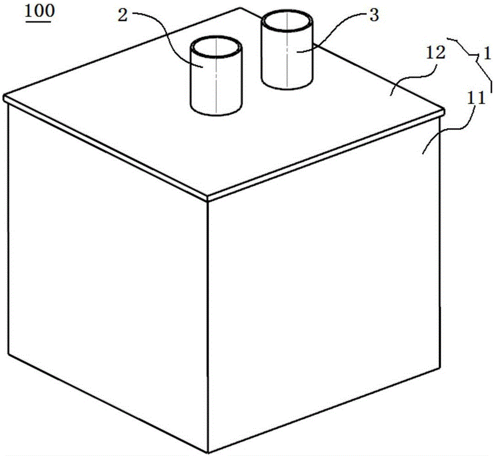
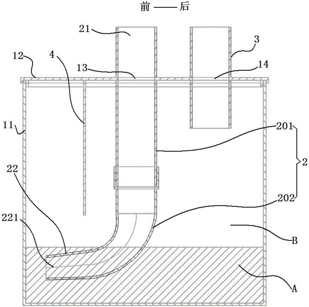
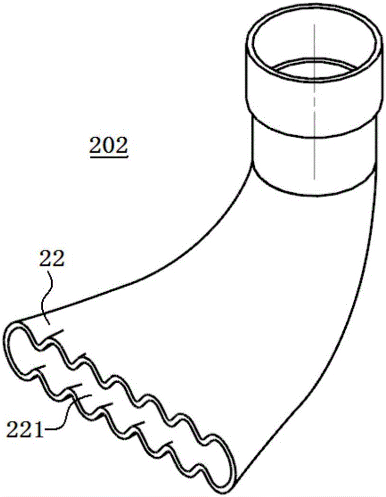
The invention discloses a filtering assembly and a dust collector with the same. The filtering assembly comprises a box body and an air intake pipe, wherein the box body is filled with liquid and provided with an air inlet and an air outlet, the air intake pipe is connected with the air inlet, the air outlet end of the air intake pipe is positioned inside the box body and extends towards the liquid or is submerged in the liquid, and the cross section area of the air intake pipe gradually increases along the flowing direction of fluid inside the air intake pipe. According to the filtering assembly, the air outlet end of the air intake pipe is fabricated into a diffuser so as to effectively reduce flow speed of air containing dust injected into the liquid by the air intake pipe, increase the mixing time and contact area between the air containing dust and the liquid, mix the air containing dust with the liquid better, improve filtering effect, decrease impacts of gas phase and liquid phase, effectively suppress noise produced during burst of bubbles, reduce height of splashed water, and facilitate gas-liquid separation.

Description

Technical field [0001] The present invention relates to the field of cleaning equipment, in particular to a filter assembly and a vacuum cleaner having the same. Background technique [0002] The filter water tank is the core component of the water filter vacuum cleaner. It uses clean water as the filter material to replace the dust cup, dust box and other structures commonly used in traditional vacuum cleaners. It does not require additional replacement of dust bags, HEPA nets and other consumables. Moreover, the water filter dust is obvious, and the dust can be dumped directly after being mixed with water, without causing the problem of dusting, so as to achieve the ultimate cleaning effect. The intake pipe in the filter water tank is an important component, and its performance will directly affect the water's ability to filter dusty gas and the subsequent water-gas separation effect. [0003] Some air intake pipes in the related art are circular pipes with equal cross-sections ...

Claims


Application Information

Patent Timeline
Patent Type & Authority Applications(China)
IPC IPC(8): A47L9/18
CPCA47L9/185A47L9/187
Inventor 张辉明乐乐张冀喆张朝磊徐前
Owner MIDEA GRP CO LTD
Why Eureka
Try Eureka