
Optimal Design Method of Concrete Floor Slabs for Alleviating Earthquake Damage of Strong Beams and Weak Columns

An optimized design and concrete technology, applied to floors, buildings, building components, etc., to avoid earthquake damage of strong beams and weak columns, avoid cracking, and ensure normal use

Inactive Publication Date: 2019-02-19
郭猛
View PDF7 Cites 0 Cited by
  • Summary
  • Abstract
  • Description
  • Claims
  • Application Information

AI Technical Summary

Problems solved by technology

[0005] Therefore, a technical problem that needs to be urgently solved by those skilled in the art is: how to propose a concrete floor design method to ensure that plastic hinges are formed at the ends of frame beams first, so as to reduce or avoid earthquake damage of strong beams and weak columns under earthquake action, and at the same time Ensure the continuity of the floor, reduce or avoid the cracking of the floor caused by the installation of gaps or seismic isolation devices, and facilitate people to use

Method used


Image

  • Optimal Design Method of Concrete Floor Slabs for Alleviating Earthquake Damage of Strong Beams and Weak Columns
  • Optimal Design Method of Concrete Floor Slabs for Alleviating Earthquake Damage of Strong Beams and Weak Columns
  • Optimal Design Method of Concrete Floor Slabs for Alleviating Earthquake Damage of Strong Beams and Weak Columns

Examples


Embodiment Construction

[0025] The present invention provides a concrete floor optimization design method for alleviating earthquake damage of strong beams and weak columns. The present invention will be further described below through the description of drawings and specific implementation methods.

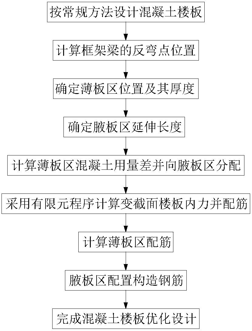
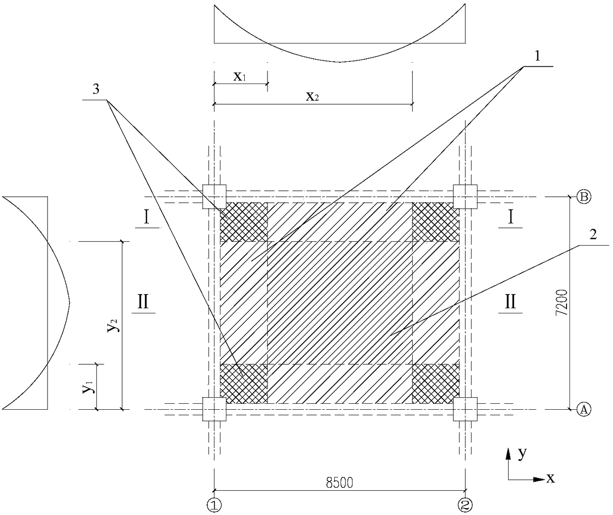
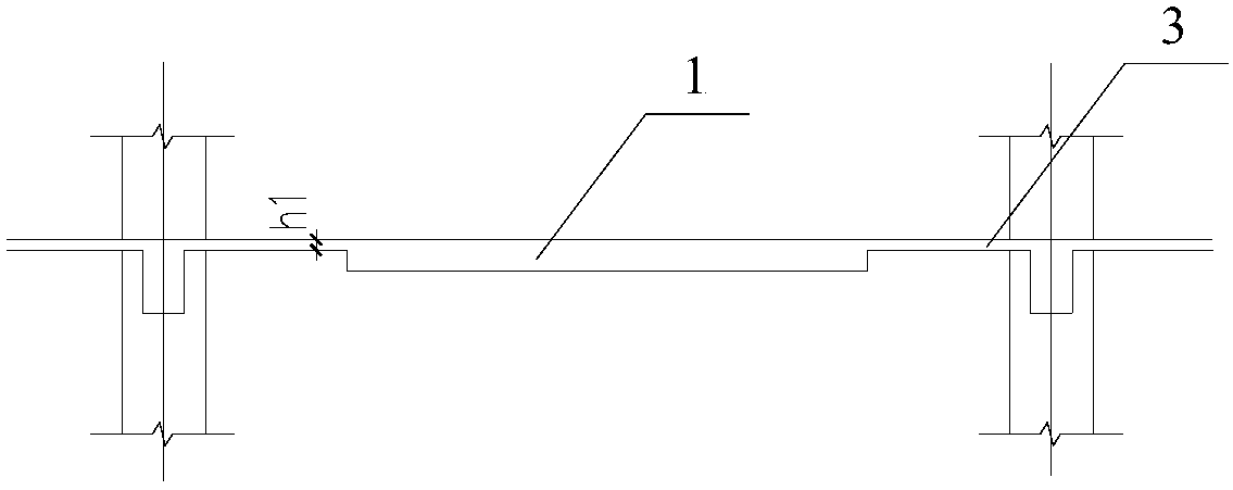
[0026] refer to Figure 1 ~ Figure 4 , shows a specific embodiment of the concrete floor slab and its design method of the present invention.

[0027] Frame structure column net size 8.5×7.2m, X direction 8.5m, Y direction 7.2m, frame column section 800×800mm, frame beam section 400×800mm, floor span 8100×6800mm, live load standard value 2.0kN / m 2 , additional dead load standard value 2.0kN / m 2 , concrete strength C30, longitudinal reinforcement HRB335, longitudinal reinforcement protective layer thickness 15mm, frame beam support reinforcement 8 φ 25.

[0028] Step 1. According to parameters such as floor span, material strength, and load conditions, the floor thickness h is preliminarily determine...


PUM


Abstract

The invention discloses a concrete floor optimized design method capable of relieving earthquake damages on strong beams and weak columns. The concrete floor optimized design method mainly comprises the following steps: calculating a floor thickness according to a conventional design method; calculating the location of a framework beam inflection point; determining a thin plate area range, thicknesses of plates within the thin plate area and a haunch plate area range; calculating concrete use difference within the thin plate area range, and distributing concrete towards the haunch plate area range to form a variable-section floor; and carrying out variable-section floor reinforcement design and thin plate area reinforcement design, thereby completing the concrete floor optimized design capable of relieving earthquake damages on strong beams and weak columns. According to the design method, the section height and the reinforcement quantity of adjacent floors in a framework beam hogging moment zone are reduced, hogging moment stress level when floor reinforcing steel bars participate in a framework beam is reduced, earthquake damages, caused by floor reinforcing effect, on the strong beams and weak columns are effectively relieved or almost avoided, and the anti-seismic design demand of the strong beams and weak columns are met.

Description

technical field [0001] The invention relates to a concrete floor optimization design method for reducing earthquake damage of strong beams and weak columns, belonging to the technical field of building structures. Background technique [0002] The frame structure is a load-bearing structure system composed of frame beams and frame columns connected in the form of rigid knots. In order to ensure the seismic safety of the frame structure and avoid the failure of vertical members before horizontal members, the internal force distribution of frame beams and frame columns must be adjusted during structural design, following the principles of strong columns and weak beams, strong shear and weak bends, and strong joints and weak bars. The meaning of strong column and weak beam is to ensure that the damage of the frame structure occurs first at the beam end under earthquake action, that is, the plastic hinge is first formed at the beam end, and the beam end is damaged before the colu...

Claims


Application Information

Patent Timeline
Patent Type & Authority Patents(China)
IPC IPC(8): E04B5/43
CPCE04B5/43E04B2103/02
Inventor 郭猛
Owner 郭猛
Learn More