Stator structure of compact permanent magnet brushless structure

A permanent magnet brushless motor and stator structure technology, applied in the direction of magnetic circuit shape/style/structure, magnetic circuit, electrical components, etc., can solve problems such as motor performance degradation, motor positioning torque fluctuations, etc., to reduce weight and improve Power density, effect of reducing overall length

Active Publication Date: 2016-06-29
HARBIN INST OF TECH
View PDF7 Cites 0 Cited by
  • Summary
  • Abstract
  • Description
  • Claims
  • Application Information

AI Technical Summary

Problems solved by technology

[0007] The purpose of the present invention is to solve the problem that directly embedding the Hall element in the stator slot of the existing stator structure will cause fluctuations in the positioning torque of the motor, resulting in a decrease in the performance of the motor, and provides a stator structure for a compact permanent magnet brushless motor

Method used


Image

  • Stator structure of compact permanent magnet brushless structure
  • Stator structure of compact permanent magnet brushless structure

Examples


specific Embodiment approach 1

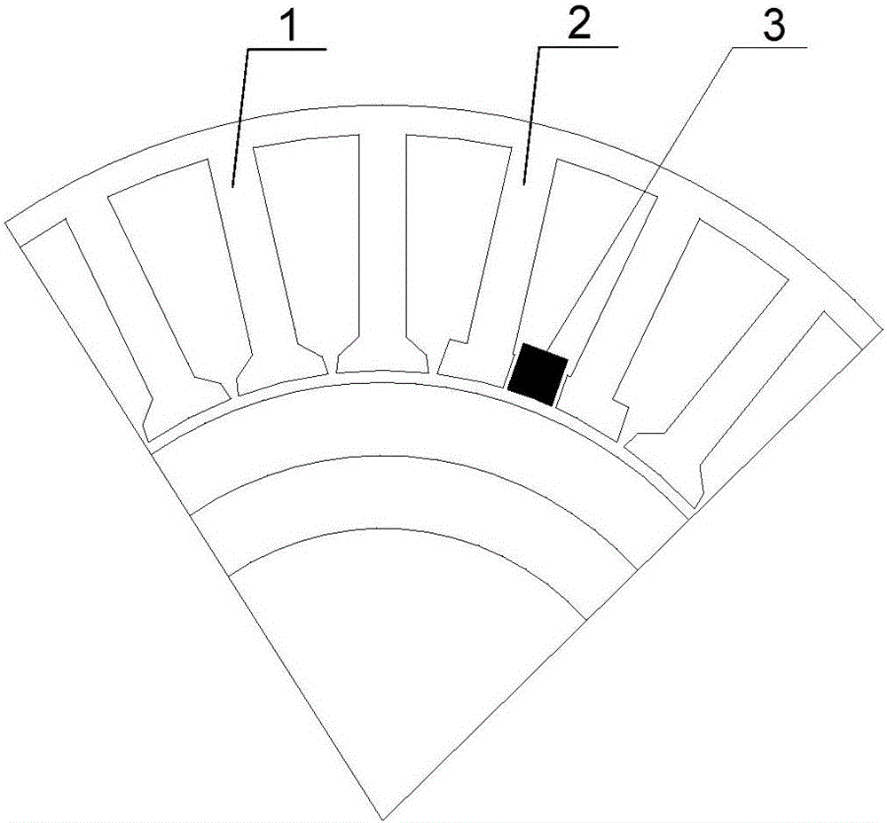
[0013] Specific implementation mode one: the following combination figure 1 with figure 2 Describe this embodiment, the stator structure of a compact permanent magnet brushless motor described in this embodiment, the stator structure includes a stator core and a plurality of stator teeth, a plurality of stator teeth are uniformly arranged on the inner circular surface of the stator core, all stators The inner surface of the tooth is located on the same circumference; a stator slot is formed between every two stator teeth, and three Hall elements 3 are embedded in the stator slot in a three-phase symmetrical manner, and each Hall element 3 is located in the stator slot. The two stator teeth are two special teeth 2 arranged symmetrically in mirror images, and the stator teeth in other positions are normal stator teeth 1; the pole shoe on the side of the special teeth 2 facing the Hall element 3 is nearly missing, and the special teeth 2 are away from the Hall element 3. The po...

specific Embodiment approach 2

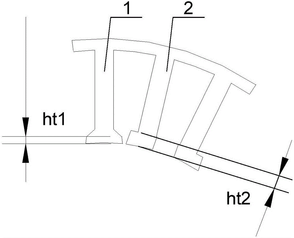
[0017] Specific implementation mode 2: This implementation mode further explains the implementation mode 1, and this implementation mode provides a specific example of parameter matching ht2=2.5ht1. But not limited to this example.

[0018] ht1 should be significantly smaller than ht2, the purpose is to make the magnetic density distribution at the air gap where the special tooth 2 is located very close to the air gap magnetic density distribution at the normal stator tooth 1, and the shoulders of the teeth will not be too saturated to achieve a uniform distribution of the air gap magnetic density The purpose is to minimize the cogging torque and torque fluctuation.


PUM


Abstract

The invention discloses a stator structure of a compact permanent magnet brushless motor, and belongs to the field of the motor. According to the structure provided by the invention, the problem of reducing the performance of the motor resulting from fluctuation of the positioning torque of the motor is solved, wherein the fluctuation of the positioning torque results from directly embedding Hall elements in the stator slots of the stator structure. The stator structure provided by the invention comprises a stator iron core and multiple stator teeth. The multiple stator teeth are evenly arranged on the surface of the inner circle of the stator iron core; the surfaces of the inner circles of all stator teeth are located on the same circle; a stator slot is formed between every two stator teeth; three Hall elements are embedded in the stator slots in a three-phase symmetrical mode; two stator teeth of the stator slot in which each Hall element is located are two special teeth arranged in a mirror symmetry mode; the stator teeth at other locations are normal stator teeth; the pole shoes at the sides of the special teeth facing towards the Hall elements are approximate to deletion; and the thicknesses ht2 of the pole shoes at the sides of the special teeth depart from the Hall elements are much more than the thicknesses ht1 of the pole shoes of the normal stator teeth.

Description

technical field [0001] The invention relates to a special groove structure design of a high power density segmented permanent magnet brushless motor for a mechanical arm, and belongs to the technical field of motors. Background technique [0002] The space robotic arm is an important device necessary for space engineering, assisting astronauts to complete high-precision transportation and maintenance work. The design requirements of the mechanical arm are high strength, high reliability, flexible work and light volume and weight as possible. Electromagnetic devices are essential in the manipulator drive system. Compared with hydraulic drive and other common drive methods for ground manipulators, electromagnetic drive has great advantages in the space field. Therefore, as far as the current development of the space field is concerned, other countries with advanced space science and technology have adopted electromagnetic drive methods to solve the drive problem of space man...

Claims


Application Information

Patent Timeline
Patent Type & Authority Applications(China)
IPC IPC(8): H02K1/16H02K29/08
CPCH02K1/165H02K29/08
Inventor 尚静刘雪缘刘承军胡建辉李昕珏江善林邹继斌徐永向李勇
Owner HARBIN INST OF TECH
Why Eureka
Try Eureka