PM stepper motor injection-molded rotor and manufacturing method thereof

A stepper motor and injection molding technology, which is used in the manufacture of stator/rotor bodies, electrical components, electromechanical devices, etc., can solve the problems of insufficient bonding force between the shaft and injection molding, difficulty in automation, and low production efficiency, and achieve high production efficiency. , the effect of strong versatility and low cost

Inactive Publication Date: 2016-06-29
SHANGHAI MOONS ELECTRICAL APPLIANCE
View PDF6 Cites 1 Cited by
  • Summary
  • Abstract
  • Description
  • Claims
  • Application Information

AI Technical Summary

Problems solved by technology

[0005] 1. Due to the processing of knurls (or grooves) on the shaft, the production efficiency of the shaft is low, the delivery time is long and the cost is high.
[0006] 2. Due to the space limitation of processing knurling (or groove), the bonding area with the injection molding material is small, resulting in insufficient bonding force between the shaft and the injection molding material
[0007] 3. In terms of technology, the hardness of the shaft and the knurling (or groove) requirements are relatively high. If the control is not good, it is easy to cause the shaft to break
[0009] 1. Since the aluminum sleeve (or copper sleeve) is a metal processing part, there will be problems of low production efficiency, long delivery time and high cost
[0010] 2. Press the aluminum sleeve (or copper sleeve) on the shaft, and finally inject it into an integrated one. This process is difficult to automate

Method used


Image

  • PM stepper motor injection-molded rotor and manufacturing method thereof
  • PM stepper motor injection-molded rotor and manufacturing method thereof
  • PM stepper motor injection-molded rotor and manufacturing method thereof

Examples


Embodiment

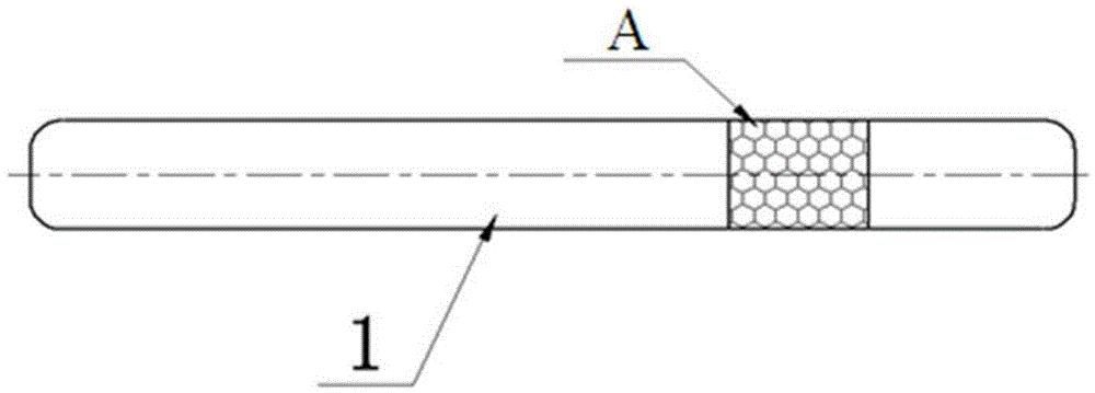
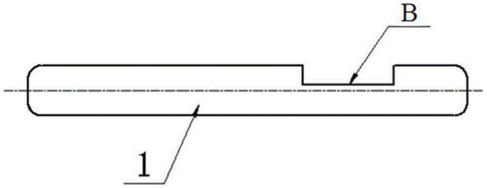
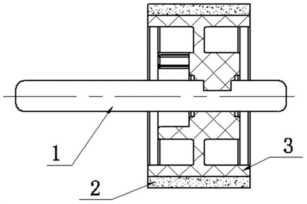
[0040] like Figure 7-9 As shown, a PM type stepper motor injection molded rotor includes a shaft 1, a magnet frame 5, a magnetic material layer 2 and an injection molding structure 3, the magnet frame 5 is fixedly sleeved on the shaft 1, and the magnet frame 5 is connected to the injection molding structure 3 The magnetic material layer 2 is injection molded into one body, and the inner diameter of the magnet frame 5 is connected with the shaft 1 by interference fit.

[0041] The magnet frame 5 is a boss structure, and the center of the boss structure is provided with a circular hole for shaft penetration.

[0042] The manufacturing method of PM type stepper motor injection molding rotor of the present invention comprises

[0043] 1) Utilize the mold to process the magnet frame 5 of the boss structure, the magnet frame 5 is provided with a central through hole and a card slot is provided on the outer circumference of the boss base;

[0044] 2) Press the shaft into the magne...


PUM


Abstract

The invention relates to a PM type stepping motor injection molded rotor and a manufacturing method thereof, comprising a shaft, a magnet frame, a magnetic material layer and an injection molding structure, the magnet frame is sleeved on the shaft, and the magnet frame is connected with the injection molding structure through the injection molding structure The magnetic material layer is injection molded into one body, and the inner diameter of the magnet frame is connected with the shaft by interference fit; wherein the manufacturing method includes the following steps: 1) processing the magnet frame with a boss structure by using a mold, the magnet frame is provided with a central through hole and A card slot is provided on the outer circumference of the boss base; 2) Press the shaft into the magnet frame described in step 1, and connect it with the inner diameter of the magnet frame with an interference fit; 3) Inject the pressed magnet frame and the magnetic material layer into a One. Compared with the prior art, the invention has the advantages of high reliability, high production efficiency and low manufacturing cost.

Description

technical field [0001] The invention relates to an injection molding rotor, in particular to a PM type stepping motor injection molding rotor and a manufacturing method thereof. Background technique [0002] There are generally two methods in the prior art for PM-type stepper motor injection molding rotors. The first method is to knurling on shaft 1 (such as figure 1 ) or machine a small groove on axis 1 (such as figure 2 ), and finally the shaft, the injection molding material 3, and the magnetic material 2 are injection molded together (such as image 3 ); the second way is to knurling on the aluminum sleeve 4 (or copper sleeve) (such as Figure 4 ), and then press the shaft into the aluminum sleeve 4 (or copper sleeve) (such as Figure 5 ), and finally integrated with magnetic material injection molding (such as Image 6 ). [0003] The defective that existing technology exists has: [0004] The first approach: [0005] 1. Due to the processing of knurls (or groov...

Claims


Application Information

Patent Timeline
Patent Type & Authority Applications(China)
IPC IPC(8): H02K37/10H02K1/22H02K15/03
Inventor 蔡乃冰何欣
Owner SHANGHAI MOONS ELECTRICAL APPLIANCE
Why Eureka
Try Eureka