Tubular continuous liquid-liquid extraction device and operation method thereof

An operation method and technology of an extraction device, which are applied in the field of liquid-liquid extraction equipment, can solve the problems that the production process cannot be well satisfied, cannot be operated for a long period of time, and the equipment occupies a large area. The effect of long production cycle

Inactive Publication Date: 2016-07-06
SHENYANG INSTITUTE OF CHEMICAL TECHNOLOGY +1
View PDF3 Cites 9 Cited by
  • Summary
  • Abstract
  • Description
  • Claims
  • Application Information

AI Technical Summary

Problems solved by technology

Some of the above-mentioned extraction equipment are huge, occupy a large area, require a lot of investment, and have high operating costs; some cannot run f

Method used


Image

  • Tubular continuous liquid-liquid extraction device and operation method thereof
  • Tubular continuous liquid-liquid extraction device and operation method thereof
  • Tubular continuous liquid-liquid extraction device and operation method thereof

Examples


Embodiment 1

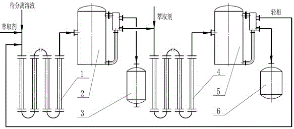
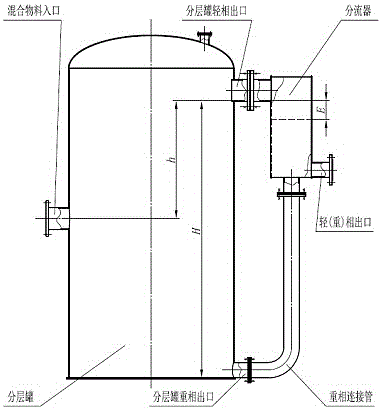
[0027] The extraction phase after the mixed liquid to be separated is extracted is the light phase. A tubular continuous liquid-liquid extraction device, the first-stage tubular extractor (1) and the second-stage tubular extractor (4) are composed of straight pipes and elbows with chemical fillers inside; the first-stage extractor used The structure of the phase and raffinate phase separator (2) and the secondary extract phase and raffinate phase separator (5) is as follows image 3 ; Primary tubular extractor (1), primary extract phase and raffinate phase separator (2), extract phase storage tank (3), secondary tubular extractor (4), secondary extract phase and raffinate The layout of phase separator (5), raffinate phase storage tank (6) and connecting pipelines between equipment is as follows: figure 1 .

[0028] The mixed liquid to be separated and the extractant enter the first-stage tubular extractor (1) while flowing and mixing for the first-stage extraction, and the m...

Embodiment 2

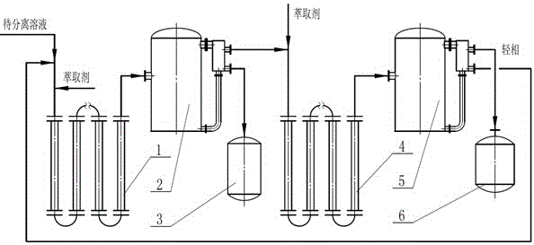
[0030] Embodiment 2 is basically the same as Embodiment 1, except that after the mixed liquid to be separated is subjected to extraction operation, the extraction phase is a heavy phase; the equipment used and the arrangement of connecting pipelines between equipment are as follows: figure 2 .

[0031] The mixed solution to be separated and the extractant enter the first-stage tubular extractor (1) while flowing, mixing, and perform primary extraction; the mixed solution exiting the first-stage tubular extractor (1) enters the first-stage extraction phase and raffinate The phase separator (2) is used for separation, and the separated raffinate phase (light phase) flows out from the light phase outlet of the splitter of the primary extraction phase and the raffinate phase separator (2), and another stream of extractant enters the secondary pipe The extractor (4) performs secondary extraction while flowing, mixing, and extraction; the extraction phase (heavy phase) separated by...

Embodiment 3

[0033] Example 3 is basically the same as Example 1, except that the first-stage tubular extractor (1) and the second-stage tubular extractor (4) used are composed of a commercially available static mixer and an elbow.


PUM


Abstract

The invention relates to a tubular continuous liquid-liquid extraction device and an operation method thereof. The tubular continuous liquid-liquid extraction device comprises continuous tubular extractors (1) and (4) and continuous extract phase and raffinate separators (2) and (5). The operation method comprises the following steps: mixing and extracting a flowing to-be-separated solution and a flowing extraction agent in the first-level tubular exactor (1); separating the extract phase from the raffinate of the material from the first-level tubular exactor (1) in the first-level extract phase and raffinate separator (2), feeding the extract phase into an extract phase storage tank (3) and mixing and extracting the flowing raffinate and another flowing extraction agent in the second-level tubular exactor (4); and separating the extract phase from the raffinate of the material from the second-level tubular exactor (4) in the second-level extract phase and raffinate separator (5) for the second time, feeding the raffinate into a raffinate storage tank (6) and returning the extract phase to the first-level tubular exactor (1). The tubular continuous liquid-liquid extraction device has the advantages of simple structure, less investment, high operating flexibility, low running cost and high extraction and separation efficiency.

Description

technical field [0001] The invention relates to a chemical unit operating equipment and an operating method thereof, in particular to liquid-liquid extraction equipment and an operating method. Background technique [0002] The operation of extracting a certain component in the solution to be separated with another liquid (extractant) is called liquid-liquid extraction, which is an important chemical unit operation. Due to the diversity of the liquid-liquid extraction process, people have invented a variety of extraction equipment for various occasions. Commonly used extraction equipment includes mixing and settling tanks or stirred tanks using mechanical agitation, spray extraction towers, plate extraction towers, packed extraction towers, rotary disk extraction towers, pulse sieve plate extraction towers, centrifugal extractors, impinging flow extractors, supergravity extraction towers, etc. extractor etc. Regardless of the structure of the extraction equipment used, in ...

Claims


Application Information

Patent Timeline
IPC IPC(8): B01D11/04
CPCB01D11/0426
Inventor 吴剑华
Owner SHENYANG INSTITUTE OF CHEMICAL TECHNOLOGY
Why Eureka
Try Eureka