
Double-powder quick molding and uniform spreading device

A technology of metal powder and powder spreading device, which is applied in the direction of process efficiency improvement, additive manufacturing, additive processing, etc., and can solve the problems that cannot satisfy the adjustable additive manufacturing of various material components, and do not have multi-component adjustable functions. , to achieve the effect of even laying, reducing time and improving work efficiency

Inactive Publication Date: 2016-07-06
NANJING UNIV OF SCI & TECH
View PDF7 Cites 17 Cited by
  • Summary
  • Abstract
  • Description
  • Claims
  • Application Information

AI Technical Summary

Problems solved by technology

[0005] CN104890240A discloses a nano-powder laser selective melting additive manufacturing system and method. The device and method use nano-materials as selective laser sintering materials, which can improve the performance and surface quality of selective laser sintering. However, such equipment is currently only applicable to Based on one nano powder material, it cannot meet the requirements of adjustable additive manufacturing of various material components.
Although this method uses two kinds of powder materials, they are mixed by ball milling according to a certain ratio before forming, so it does not have the function of multi-component adjustment, nor can it meet the requirements of multi-material component adjustable additive manufacturing.

Method used


Image

  • Double-powder quick molding and uniform spreading device
  • Double-powder quick molding and uniform spreading device
  • Double-powder quick molding and uniform spreading device

Examples


Embodiment 1

[0031] Embodiment 1, select a kind of powder a to carry out additive manufacturing, as Figure 3a As shown, the specific additive manufacturing steps are as follows:

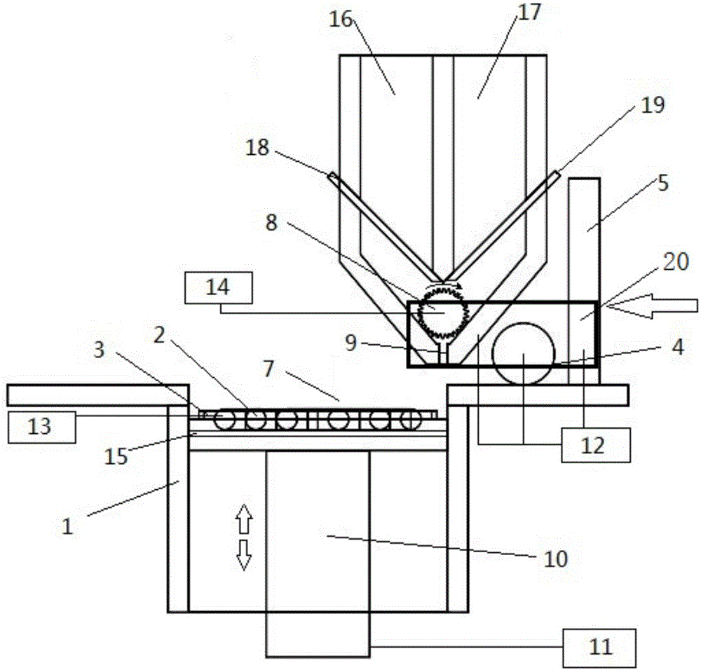
[0032] Step 1, using a two-chamber powder supply box, and putting powder a into the first chamber 6 according to the determined powder material.

[0033] Step 2, preparation before spreading powder. Place the target substrate 15 with a thickness of d1 on the lifting platform 10 at a height parallel to the worktable, turn on the heating system, and heat the target substrate 15 to a predetermined temperature T1, which is controlled by feedback from the temperature monitoring system.

[0034] Step 3, open the first chamber switch 18, and pre-lay a layer of powder material with a thickness of D 0 .

[0035] Step 4, first spread powder, such as Figure 4a shown. Determine to select powder for use, open switch 18, select powder a for use, select the automatic control button, then press the start button. In the m...

Embodiment 2

[0040] Example 2, two kinds of powders a and b are selected for additive manufacturing, as shown in Figures 3 and 4, and the specific additive manufacturing steps are as follows:

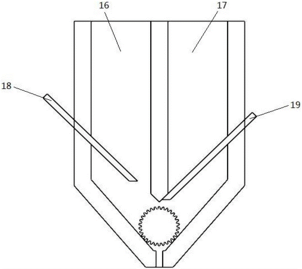
[0041] Step 1, using a two-chamber powder supply box, according to the determined powder material, put powder a into the first chamber 16 and put powder b into the second chamber 17 .

[0042] Step 2, preparation before spreading powder. Place the target substrate 15 with a thickness of d1 on the lifting platform, the height is parallel to the worktable, turn on the heating system, and heat the target substrate 15 to a predetermined temperature T1, which is controlled by the feedback of the temperature monitoring system.

[0043] Step 3, turn on the first chamber switch 18 and the second chamber switch 19, mix the powder e according to a certain ratio, and pre-lay a layer of powder material with a thickness of D 0 ,

[0044] Step 4, first spread powder, such as Figure 4a shown. Determine to sel...

Embodiment 3

[0049] Embodiment 3, select three kinds of powder a, b, c to carry out additive manufacturing, as Figure 5a -d, the specific additive manufacturing steps are as follows:

[0050] Step 1, using a two-chamber powder supply box, according to the determined powder material, put powder a into the first chamber 16, powder b into the second chamber 17, and powder c into the third chamber 25 .

[0051] Step 2, preparation before spreading powder. Set the thickness to d 1 The target substrate 15 is placed on the lifting platform, the height is parallel to the worktable, the heating system is turned on, and the target substrate 15 is heated to a predetermined temperature T 1 , controlled by the temperature monitoring system feedback.

[0052] Step 3, open the first chamber switch 18, and pre-lay a layer of powder material with a thickness of D 0 .

[0053] Step 4, first spread powder, such as Figure 4a shown. Determine to select powder for use, open switch 19, select powder b ...


PUM


Abstract

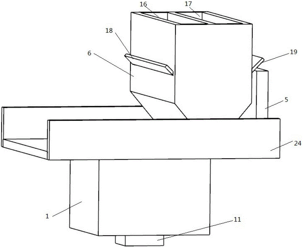
The invention aims to provides a double-powder quick molding and uniform spreading device which comprises a lifting working platform, a linear module fixedly connected with the lifting working platform, a powder pressing roller arranged on a linear module sliding block, a powder scraper, a powder supply body, a lifting platform arranged in a working platform molding cylinder and a heating device arranged on the lifting platform, wherein a baffle is arranged in the powder supply box to divide the powder supply box into a plurality of chambers with the same volume; a switch for controlling the falling of a powder is arranged at a powder outlet part of each chamber; a powder supply shaft with a gear-shaped section is arranged at a powder outlet of the powder supply box; and the powder supply shaft is tangent to a wedged edge of the powder outlet of the powder supply box. The double-powder quick molding and uniform spreading device realizes quick molding of two powders at any ratio on each layer according to a two-dimensional diagram, ensures that all layers of a molded part have gradient differences, and thus reduces time waste caused by the reason that only one powder can be used in one cycle. The double-powder quick molding and uniform spreading device can uniformly heat the powders that a high energy density beam acts on, detect a temperature field and control interpass temperature, thus reducing residual stress caused by nonuniform temperature.

Description

technical field [0001] The invention belongs to the field of mechanical design and manufacture, and in particular relates to a uniform powder spreading device suitable for various metal powders. Background technique [0002] Powder spreading is one of the important links of rapid prototyping technology, and the effect of powder laying directly affects the molding effect. However, there are many forms of powder laying, and most of the existing single-cycle laying metal powders have only one type. In order to realize the rapid prototyping of multiple powder functional gradients, the powder must be re-injected, so a lot of time is wasted and work efficiency is reduced. The existing powder spreading methods are divided into upper powder feeding and lower powder feeding. The existing method of upper powder supply and powder spreading can only use one type of powder for rapid prototyping at a time, which cannot realize the rapid prototyping of various metal materials, thus hinder...

Claims


Application Information

Patent Timeline
IPC IPC(8): B22F3/105B33Y30/00
CPCB33Y30/00B22F10/00B22F12/90B22F12/52B22F12/57B22F10/34B22F12/58B22F12/17B22F10/28Y02P10/25
Inventor 周琦王超宁刘和义彭勇孔见王克鸿杜坤张业成郭顺冯曰海付贝贝李洪强
Owner NANJING UNIV OF SCI & TECH
Learn More