
Sponge urban unit system

A technology of unit system and sponge city, applied in the field of sponge city unit system, can solve problems such as water shortage, environmental pollution, waterlogging, etc., and achieve the effects of eliminating heat island effect, reducing environmental pollution, greening and beautifying the city

Active Publication Date: 2016-07-06
PEKING UNIV
View PDF8 Cites 6 Cited by
  • Summary
  • Abstract
  • Description
  • Claims
  • Application Information

AI Technical Summary

Problems solved by technology

[0005] The technical problem to be solved by the present invention is to provide a method that can retain urban rainwater, purify, recycle, digest and absorb urban sewage and urban organic waste at the same time, and solve environmental pollution, water resource shortage, and urban waterlogging caused by cities. , urban heat island effect and other issues of sponge city unit system

Method used


Image

  • Sponge urban unit system

Examples


Embodiment 1

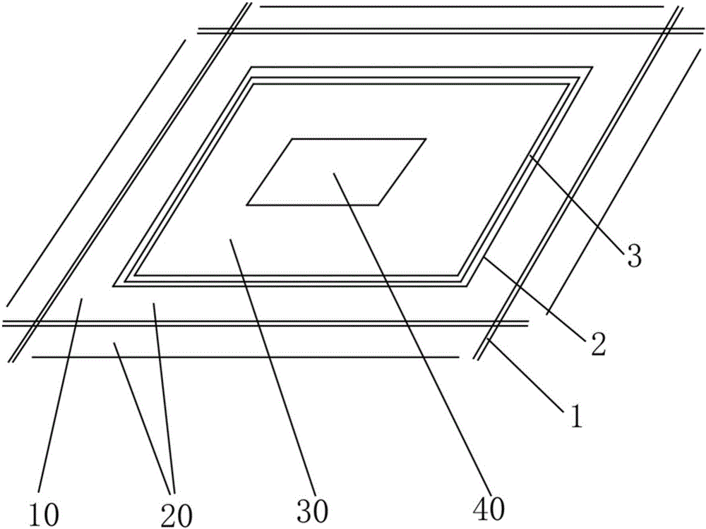
[0028] Such as figure 1 Shown is an embodiment of the sponge city unit system of the present invention.

[0029] The sponge city unit system of the first embodiment includes: the main road 1 around the city, the circular walkway 2 and the circular river channel 3 . Among them, the surrounding urban main road 1 encloses the synthetic planning area 10, the circular walkway 2 and the circular river course 3 are located in the planning area 10, and the circular walkway 2 is located outside the circular river course 3, that is, the circular walkway 2 is located in the surrounding cities Between the main road 1 and the ring channel 3. A building area 20 is provided in the planning area 10. In the first embodiment, the building area 20 is formed between the circular walkway 2 and the surrounding urban main roads 1, so that the building area 20 is distributed along the surrounding urban main roads 1 sides. The ring channel 3 is used to collect rainwater in the planning area 10 . I...

Embodiment 2

[0037] Embodiment 2 is an embodiment of applying the sponge city unit system of the present invention to the planning and design of urban functional service areas, taking Beijing as an example.

[0038] The Sixth Ring Road is the dividing line between the urban area and the suburbs of Beijing. It extends five kilometers inside and outside the Sixth Ring Road, forming a ten-kilometer-wide circular zone with an area of ​​about 1,200 square kilometers. Urban functional service areas are established in this area. The urban functional service area is planned and designed according to the sponge city unit system model of the present invention. Each sponge city unit system is a minimum of two kilometers by two kilometers, of which the urban agricultural park area covers an area of ​​about one square kilometer, so that one quarter of the urban land is used for the urban agricultural park area. Three railway passenger stations of the same scale shall be established in the south, east a...


PUM


Abstract

The invention relates to the technical field of urban planning design and urban water conservancy facilities, in particular to a sponge urban unit system.The system comprises a surrounding urban main road and an annular watercourse, wherein a planning region is defined by the surrounding urban main road, and a building region is arranged in the planning region; the annular watercourse is located in the planning region to be used for collecting rainwater in the planning region; an urban agricultural garden region is defined by the annular watercourse, an urban waste disposal region is arranged in the urban agricultural garden region, and sewage pipelines used for guiding sewage in the building region to the urban waste disposal region are laid in the planning region.In this way, urban rainwater is kept in cities, disposed locally and recycled, urban sewage and organic waste are digested and absorbed, urban afforestation and beautification can be achieved through the urban agricultural garden region, the agricultural product requirement of cities can be provided partially, ecological cities are realized, and environment pollution, water resource shortage, urban inland inundation, urban heat island effect and other city problems are solved.

Description

technical field [0001] The invention relates to the technical field of urban planning and design and urban water conservancy facilities, in particular to a sponge city unit system. Background technique [0002] With the continuous development of cities, many "over-urbanization" phenomena have emerged, resulting in a series of contradictions and problems called "urban diseases": traffic congestion, environmental pollution, water shortage, urban waterlogging, urban heat island effect, etc. Wait. [0003] Every detail of urban planning and construction must consider the impact on nature, let alone break the natural system. Why are so many cities short of water? An important reason is that there are too many concrete floors, which occupy forest land, grassland, lakes, and wetlands that can conserve water sources, cutting off the natural water cycle. When rainwater comes, it can only be drained away as sewage, and the groundwater is getting less and less. To solve the problem ...

Claims


Application Information

Patent Timeline
IPC IPC(8): E03F1/00E03F3/02
CPCE03F1/00E03F1/001E03F3/02Y02A30/60
Inventor 赵鹏军季燕铜于昭刁晶晶
Owner PEKING UNIV
Learn More