Water quality monitoring system for water area of scenic spot

A water quality monitoring system and water area technology, applied in signal transmission systems, measuring devices, instruments, etc., can solve the problems of large size of wind turbines and their ancillary equipment, and achieve the effects of simple structure, small size, and increased power generation.

Inactive Publication Date: 2016-07-06
HENAN DANJIANG GRAND VIEW GARDEN TOURISM CO LTD
View PDF10 Cites 9 Cited by
  • Summary
  • Abstract
  • Description
  • Claims
  • Application Information

AI Technical Summary

Problems solved by technology

The device adopts wind-solar complementary power generation, which can ensure uninterrupted power supply, but the wind turbine and its auxiliary equipment are relatively large in size and are only suitable for installation on the shore to monitor water quality.

Method used


Image

  • Water quality monitoring system for water area of scenic spot
  • Water quality monitoring system for water area of scenic spot
  • Water quality monitoring system for water area of scenic spot

Examples


Embodiment 1

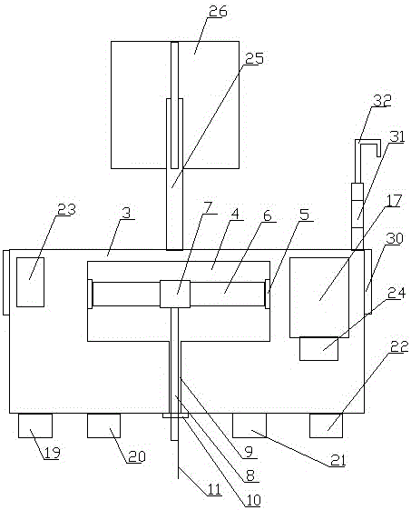
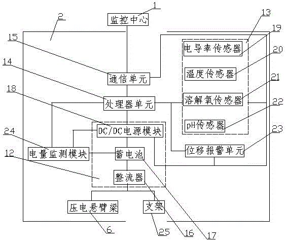
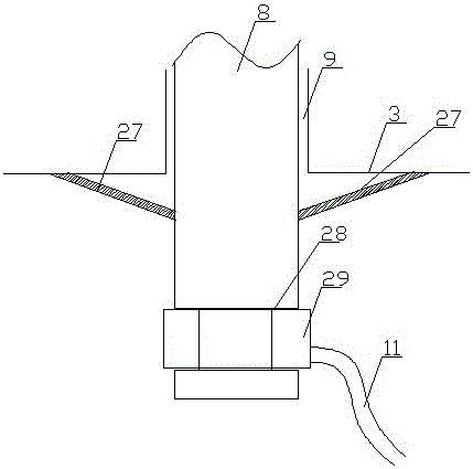
[0029] Such as figure 1 and figure 2 As shown: this embodiment provides a water quality monitoring system for scenic waters, including a monitoring center 1 and a remote node 2, the remote node 2 includes a bearing floating body 3 set on the water surface, and a cavity is arranged inside the bearing floating body 3 4. The two sides of the cavity 4 are correspondingly provided with bases 5, and piezoelectric cantilever beams 6 are arranged between the bases 5, and insulating collars 7 are fixedly arranged on the piezoelectric cantilever beams 6, and the insulating collars 7 A pull rod 8 is arranged below, and a through hole 9 is set below the bearing floating body 3 corresponding to the pull rod 8. A sealing mechanism 10 is arranged between the pull rod 8 and the through hole 9. The lower end of the pull rod 8 passes through the rope body 11 and the bottom of the water. Fixedly connected, the piezoelectric cantilever beam 6 is connected to a power management unit 12 , and the...

Embodiment 2

[0035] Such as figure 1 and figure 2 As shown: this embodiment also provides a water quality monitoring system for scenic waters, including a monitoring center 1 and a remote node 2, the remote node 2 includes a bearing floating body 3 set on the water surface, and a cavity is arranged inside the bearing floating body 3 body 4, bases 5 are arranged correspondingly on both sides of the cavity 4, piezoelectric cantilever beams 6 are arranged between the bases 5, and insulating collars 7 are fixedly arranged on the piezoelectric cantilever beams 6, and the insulating collars A pull rod 8 is arranged below the pull rod 8, and a through hole 9 is set below the bearing floating body 3 corresponding to the pull rod 8. A sealing mechanism 10 is set between the pull rod 8 and the through hole 9, and the lower end of the pull rod 8 passes through a rope body 11 and Fixedly connected to the bottom of the water, the piezoelectric cantilever beam 6 is connected to a power management unit...

Embodiment 3

[0040] Such as figure 1 and figure 2 As shown: this embodiment also provides a water quality monitoring system for scenic waters, including a monitoring center 1 and a remote node 2, the remote node 2 includes a bearing floating body 3 set on the water surface, and a cavity is arranged inside the bearing floating body 3 body 4, bases 5 are arranged correspondingly on both sides of the cavity 4, piezoelectric cantilever beams 6 are arranged between the bases 5, and insulating collars 7 are fixedly arranged on the piezoelectric cantilever beams 6, and the insulating collars A pull rod 8 is arranged below the pull rod 8, and a through hole 9 is set below the bearing floating body 3 corresponding to the pull rod 8. A sealing mechanism 10 is set between the pull rod 8 and the through hole 9, and the lower end of the pull rod 8 passes through a rope body 11 and Fixedly connected to the bottom of the water, the piezoelectric cantilever beam 6 is connected to a power management unit...


PUM


Abstract

The invention discloses a water quality monitoring system for a water area of a scenic spot. The water quality monitoring system comprises a monitoring center and a remote node. The remote node comprises a bearing floater which is arranged on water surface. The bearing floater is internally provided with a chamber. The chamber is internally provided with a piezoelectric cantilever beam. An insulated lantern ring is fixedly arranged on the piezoelectric cantilever beam. A pull bar is arranged below the insulated lantern ring. A through hole which corresponds with the pull bar is arranged at the lower part of the bearing floater. A sealing mechanism is arranged between the pull bar and the through hole. The lower end of the pull bar is fixedly connected with waterbed through a rope body. The piezoelectric cantilever beam is connected with a power supply management unit. The power supply management unit is connected with a monitoring unit, a processor unit and a communication unit. The water quality monitoring system has functions of covering wave energy to electric energy, satisfying a requirement of electric power for monitoring the water quality of the water area and creating a necessary condition for wireless monitoring of the water quality. Simple structure and relatively small size are realized. Relatively high power generation efficiency on small machines is obtained. Sufficient power generating amount can be ensured for use by the monitoring equipment.

Description

technical field [0001] The invention relates to the technical field of wireless monitoring of water quality in water areas, in particular to a water quality monitoring system for scenic water areas. Background technique [0002] In recent years, with the development of industry and the continuous improvement of people's living standards, the amount of sewage discharge has continued to increase, which has far exceeded the environmental capacity allowed by the natural purification function. The natural water quality has continued to deteriorate, seriously endangering human health and destroying the ecosystem. . In order to ensure the cleanliness of the water environment and water resources, necessary measures must be taken against the pollution sources that cause water pollution, and online monitoring of environmental water quality is very necessary. Especially for some scenic spots with mountains and water, green mountains and green waters are fundamental to attract tourists...

Claims


Application Information

Patent Timeline
Patent Type & Authority Applications(China)
IPC IPC(8): G01D21/02G08C17/02H02N2/18
CPCG01D21/02G08C17/02H02N2/185
Inventor 曹长城
Owner HENAN DANJIANG GRAND VIEW GARDEN TOURISM CO LTD
Why Eureka
Try Eureka