Wide-range optical power meter

A technology of optical power meter and wide range, which is applied in the direction of measuring circuit, measuring device, photometry, etc., can solve the problem of high cost, and achieve the effect of low cost, simple optical path and convenient use

Inactive Publication Date: 2016-07-06
BROADEX TECH
View PDF7 Cites 11 Cited by
  • Summary
  • Abstract
  • Description
  • Claims
  • Application Information

AI Technical Summary

Problems solved by technology

In order to solve the problem of wide range measurement (>90dB), the traditional solution in the industry is to use multiple photoelectric probes with different measurement power ranges in a single device to expand the range, such as Thorlabs' wide range optical power meter, its structure Figure 5 As shown, each

Method used


Image

  • Wide-range optical power meter
  • Wide-range optical power meter
  • Wide-range optical power meter

Examples


Embodiment Construction

[0021] Below in conjunction with specific embodiment, further illustrate the present invention. It should be understood that these examples are only used to illustrate the present invention and are not intended to limit the scope of the present invention. In addition, it should be understood that after reading the content taught by the present invention, those skilled in the art may make various changes or modifications to the present invention, and these equivalent forms also fall within the scope defined by the appended claims of the present application.

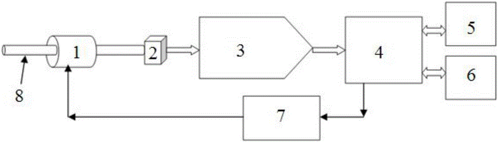
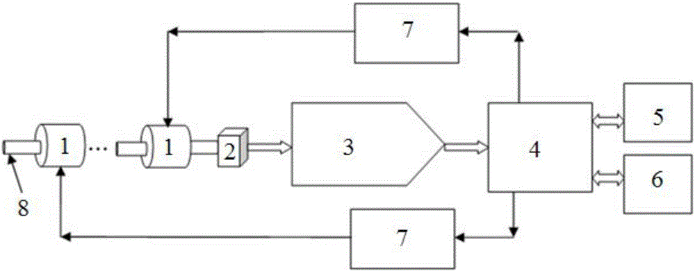
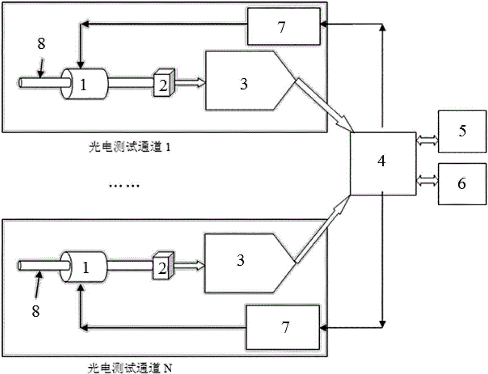
[0022] Embodiments of the present invention relate to a wide range optical power meter, such as figure 1 As shown, it includes a photodetector 2, a photoelectric signal amplification and analog-to-digital conversion sampling circuit 3, and a control calculation unit 4. The output terminal of the photoelectric detector 2 is connected to the input terminal of the photoelectric signal amplification and analog-to-digital conv...


PUM

PropertyMeasurementUnit
Attenuation valueaaaaaaaaaa
Wavelengthaaaaaaaaaa

Abstract

The invention relates to a wide-range optical power meter, which includes a photoelectric detector, a photoelectric signal amplification and analog-to-digital conversion sampling circuit, and a control calculation unit. The output terminal of the photoelectric detector is connected to the input of the photoelectric signal amplification and analog-to-digital conversion sampling circuit. The output end of the photoelectric signal amplification and analog-to-digital conversion sampling circuit is connected with the input end of the control calculation unit, and the input end of the photodetector is connected with an adjustable optical attenuator for adjusting the measurement range; The control calculation unit is also connected to the adjustable optical attenuator through an attenuation control circuit. The invention only needs to use one photodetector and a set of optical signal amplification and sampling circuits to complete the purpose of wide-range optical power signal testing, and the optical path is simple.

Description

technical field [0001] The invention relates to the technical field of optical power measurement, in particular to a wide range optical power meter. Background technique [0002] In the field of communication testing, an optical power meter is a widely used device, through which a technician or a management system can obtain the optical power value of a laser or an optical fiber. However, the measurement range of the optical power meter is limited by the measurement response range of the photodetector. Photodetectors that can test low power (such as -70dBm to -50dBm) often cannot accurately measure high power (such as 0dBm to 20dBm) optical signals, and vice versa The same is true. At present, the measurement dynamic range of a single photodetector is generally within 90dB. Figure 4 It is a typical photoelectric structure diagram of the current optical power test. The test dynamic range of the optical power meter adopting this design is consistent with the measurement dyna...

Claims


Application Information

Patent Timeline
IPC IPC(8): G01J1/44G01J1/04
CPCG01J1/4257G01J1/0418G01J1/44G01J2001/4406G01J2001/446
Inventor 文平朱伟
Owner BROADEX TECH
Why Eureka
Try Eureka