Method and device for detecting sample
A detection method and detection device technology, which is applied in the direction of measuring devices, particle and sedimentation analysis, instruments, etc., can solve the problems of detection efficiency reduction
- Summary
- Abstract
- Description
- Claims
- Application Information
AI Technical Summary
Problems solved by technology
Method used
Image

Examples
no. 1 approach
[0044] (Structure of sample detection device)
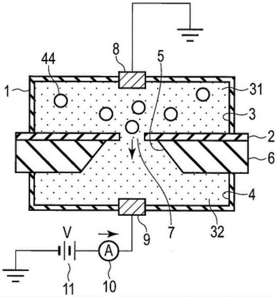
[0045] figure 1 This is a cross-sectional view showing a schematic configuration of a sample detection device used in the sample detection method according to the first embodiment.
[0046] The sample detection device is provided with a liquid-filled detection kit 1 . The detection kit 1 is divided into upper and lower parts by an insulating partition wall 2 . The first chamber 3 is formed above the partition wall 2 inside the detection kit 1 . The second chamber 4 is formed below the partition wall 2 inside the detection kit 1 . The support plate 6 is provided on the bottom surface of the partition wall 2 to support the partition wall 2 . A hole 5 in the shape of a truncated cone passes through the central portion of the support plate 6 . Minute through-holes 7 pass through the part of the partition wall 2 corresponding to the holes 5 of the support plate 6 . Therefore, the first and second chambers 3 and 4 are connected t...
no. 2 approach
[0082] In the second embodiment, two types of measurement target substances (for example, biomolecules) that may exist in a sample will be described as an example. In addition, the sample detection using the aforementioned figure 1 The sample detection device is shown.
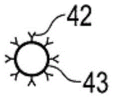
[0083] like Figure 5A As shown, the reagent contains a first capture substance 42 (such as a first antibody) that is specifically bound to the surface of the first substance to be measured and has a size (such as a diameter) that is bound to the capture substance 42 that is smaller than that of the substance to be measured. ) of the first marker particle 43 . In addition, if Figure 5B As shown, the reagent contains a second capture substance 52 (for example, a second antibody) specifically bound to the surface of the second substance to be measured, and a second label particle 53 bound to the capture substance 52 . In addition, the sizes (for example, diameters) of the first and second labeling particles...
no. 3 approach
[0091] refer to Figure 7 and Figure 8 , and the sample detection device according to the third embodiment will be described in detail.
[0092] Figure 7 It is a plan view of the sample detection device according to the third embodiment. Figure 8 for along Figure 7 Cross-sectional view of line VIII-VIII. The eg rectangular body 61 has a rectangular block 62 . The upper groove 64 and the lower groove 65 are arranged on the rectangular block 62 with the central wall 63 as a boundary. The upper cover 66 is disposed on the upper surface of the block 62 and covers the upper groove 64 . The lower cover 67 is arranged on the bottom surface of the block 62 and covers the lower groove 65 .
[0093] A hollow first chamber 68 is formed in a space defined by the upper groove 64 of the block 62 and the upper cover 66 . A hollow second chamber 69 is formed in a space defined by the lower groove 65 of the block 62 and the lower cover 67 .
[0094] The first chamber 68 is compose...
PUM
| Property | Measurement | Unit |
|---|---|---|
| diameter | aaaaa | aaaaa |
| diameter | aaaaa | aaaaa |
| diameter | aaaaa | aaaaa |
Abstract
Description
Claims
Application Information