
Magnetic flux switching brushless motor adopting single-layer stacked winding

A single-layer winding, brushless motor technology, applied in the shape/style/structure of the winding conductor, etc., can solve the problems of limiting the output and overall performance of the motor, increasing the difficulty of phase-to-phase insulation, and zero reluctance torque. Torque (power) density, reduction of insulation difficulty and cost, effect of motor torque improvement

Active Publication Date: 2016-07-06
SOUTHEAST UNIV
View PDF2 Cites 5 Cited by
  • Summary
  • Abstract
  • Description
  • Claims
  • Application Information

AI Technical Summary

Problems solved by technology

[0004] 1) Additional harmonic components and the parasitic effects they cause, such as noise, vibration, torque fluctuation, unbalanced magnetic pull, etc.;
[0005] 2) Each armature coil straddles the stator slots on both sides of a stator core unit, the coil span is fixed as the stator slot pitch, and the coil pitch angle is never equal to the rotor pole pitch, resulting in no-load induction potential of the coil The distance factor is always less than 1, which limits the amplitude of the no-load induced potential fundamental component of each phase of the flux switching motor;
[0006] 3) The salient pole effect is weakened, so that the reluctance torque is almost 0;
[0007] 4) For the double-layer concentrated winding, wires of different phase windings are placed in each stator slot, which increases the difficulty of interphase insulation, etc.
[0008] These problems are especially prominent in flux switching motors with low pitch factor and poor winding complementarity, which greatly limit the output and overall performance of the motor

Method used


Image

  • Magnetic flux switching brushless motor adopting single-layer stacked winding
  • Magnetic flux switching brushless motor adopting single-layer stacked winding
  • Magnetic flux switching brushless motor adopting single-layer stacked winding

Examples


Embodiment approach

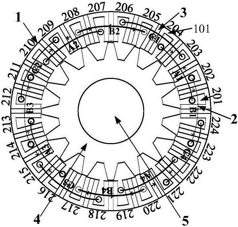
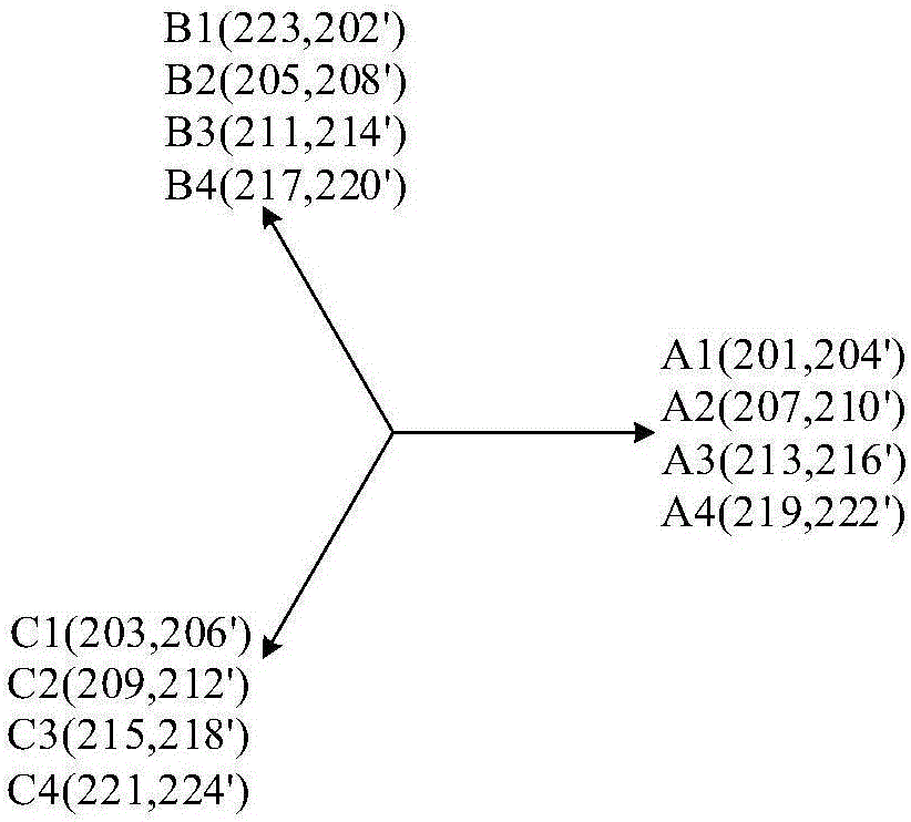
[0048] Different from the traditional flux-switching brushless motor, the single-layer stacked winding flux-switching brushless motor proposed by the present invention adopts a single-layer stacked winding connection mode, and each armature coil spans multiple stator core units, and the winding coils of different phases There is an overlap between them, and the two conductor sides of each coil occupy an entire stator slot, and are not shared with other phase coil conductors. Concrete implementation scheme is as follows:

[0049] 1) First, according to the motor stator slot number N s and the number of rotor poles N r Determine the phase difference α (electrical angle) between the no-load induced potentials of two adjacent stator slot conductors, the formula is as follows:

[0050]

[0051] Draw N in sequence s The phasor star diagram corresponding to the no-load induced potential of a slot conductor.

[0052] 2) Based on the slot conductor potential star diagram, connec...


PUM


Abstract

The invention discloses a magnetic flux switching brushless motor adopting a single-layer stacked winding. A single-layer stacked winding design method is different from the conventional dual-layer centralized winding design method, wherein according to the conventional dual-layer centralized winding design method, a fixed structure is set for enabling a coil to be corresponding to a stator iron core unit; however, according to the single-layer stacked winding design method, a stator groove for placing two conductor sides of a wire is chosen by taking the minimum short pitch angle of the coil as the principle so as to obtain the maximum pitch factor. In addition, each stator groove is used for only placing wires of windings of the same phase, so that the insulating capability of the windings of different phases is improved. Due to the winding design method provided by the invention, the pitch factor of the magnetic flux switching brushless motor reaches 1, so that the fundamental wave amplitude and power (torque) density of each phase of no-load inductive potential are improved; the difficulty of winding line inserting and insulating process is lowered; and the advantage of the magnetic flux switching brushless motor adopting the single-layer stacked winding is represented.

Description

technical field [0001] The invention belongs to the field of motor winding structure design, and relates to a single-layer stacked winding design method based on a flux-switching brushless motor. performance, suitable for high power applications. Background technique [0002] Flux switching permanent magnet motor is a new type of stator permanent magnet motor. Its stator core is assembled from a "U" shaped magnetic core and tangentially alternately magnetized permanent magnets, which is easy to form a magnetic concentration effect. The armature coil It straddles the stator slots on both sides of the stator core unit composed of two "U"-shaped permeable cores and a permanent magnet embedded in the middle, so that the armature reaction magnetic field and the permanent magnetic field are connected in parallel on the magnetic circuit, which has a strong Anti-demagnetization ability, compared with doubly salient motors and flux reversal motors, has higher torque (power) density ...

Claims


Application Information

Patent Timeline
IPC IPC(8): H02K3/28
CPCH02K3/28
Inventor 花为邵凌云程明
Owner SOUTHEAST UNIV
Learn More