
Energy-saving insulation box for tubular wet electrostatic precipitator

A wet electrostatic precipitator and insulating box technology, applied in the field of dust collectors and energy-saving insulating boxes, can solve the problems of inability to guarantee quality, waste of working time, and high power consumption, and achieve the effects of beautiful appearance, energy saving and energy saving.

Active Publication Date: 2017-08-01
海宁国能中电节能环保设备技术有限公司
View PDF10 Cites 0 Cited by
  • Summary
  • Abstract
  • Description
  • Claims
  • Application Information

AI Technical Summary

Problems solved by technology

The original insulation box must use sealed hot air, and the source of hot air is blown by a fan, and then a box heater is responsible for heating the sealed air, and the power of the fan itself is already very large, and the heater then blows the flowing air Heating to 70℃~80℃ will consume a lot of electricity, which will cause a lot of energy waste
Furthermore, the original insulation box needs to lay an insulation layer on the outside to reduce heat loss, and the insulation laying needs to be constructed on site, which wastes working time and cannot guarantee the quality

Method used


Image

  • Energy-saving insulation box for tubular wet electrostatic precipitator
  • Energy-saving insulation box for tubular wet electrostatic precipitator

Examples


Embodiment Construction

[0017] The following are specific embodiments of the present invention and in conjunction with the accompanying drawings, the technical solutions of the present invention are further described, but the present invention is not limited to these embodiments.

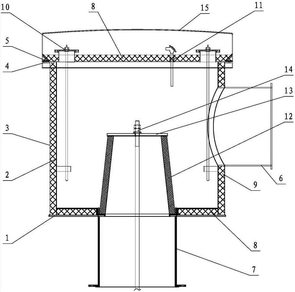
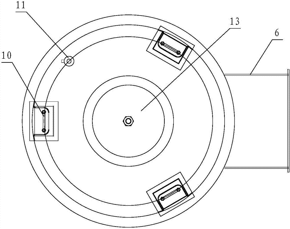
[0018] Such as figure 1 and figure 2 As shown, the energy-saving insulation box used for the tubular wet electrostatic precipitator includes a double-layer cylinder and a control cabinet. The double-layer cylinder includes a bottom plate 1, and an inner cylinder 2 and an outer cylinder 3 are fixed on the bottom plate 1. There is an insulation gap between the outer cylinder and the outer cylinder 3, the first insulation filler 9 is filled in the insulation gap, the second insulation material 8 is laid on the bottom surface of the inner cavity of the inner cylinder 2, and the tops of the inner cylinder 2 and the outer cylinder 3 are sealed and covered with a cover 5. The second thermal insulation material 8 is laid on the ...


PUM


Abstract

The invention provides an energy-saving insulated box used for a tubular wet electric dust collector. The insulated box comprises a dual-layer cylinder body and a control cabinet, wherein the dual-layer cylinder body comprises a bottom plate; an inner cylinder and an outer cylinder are fixedly arranged on the bottom plate; a heat preservation gap is reserved between the inner cylinder and the outer cylinder; the heat preservation gap is filled with a first heat preservation filler; a second heat preservation material is paved on the bottom surface of an inner cavity of the inner cylinder; the tops of the inner cylinder and the outer cylinder are hermetically covered with a cover; the second heat preservation material is paved on the top surface of the cover; a plurality of electric heating boxes are uniformly arranged on the cover; electric heating tubes are arranged in the electric heating boxes in a penetrating manner; a thermal resistor wire seat is further arranged on the cover; a thermal resistor is arranged in the thermal resistance wire seat in a penetrating manner; the electric heating tubes and the thermal resistor are connected with the control cabinet through circuits, so that the electric heating tubes and the thermal resistor form a closed loop; an insulator porcelain sleeve is arranged in the inner cavity of the inner cylinder; a suspension rod is arranged in the insulator porcelain sleeve in a penetrating manner; a lower flange short section is vertically arranged at the bottom of the bottom plate; the lower flange short section and the insulator porcelain sleeve are positioned on the same axis; and a side flange short section is arranged on a side wall of the outer cylinder.

Description

technical field [0001] The invention belongs to the technical field of flue gas desulfurization, and relates to a dust collector, in particular to an energy-saving insulating box for a tubular wet electric dust collector. Background technique [0002] Faced with the increasingly serious pollution situation of smog, aerosol, PM2.5 and heavy metals in our country, the country has issued a series of environmental protection regulations and policies to encourage enterprises to achieve ultra-clean emissions. Called by the national policy, more and more power plants are burning Large-scale desulfurization devices such as coal units or steel plant sintering machines are increasingly equipped with tubular wet electrostatic precipitators to remove acid mist, fine particles, PM2.5, aerosols, etc. in the flue gas; tubular wet electrostatic precipitators Most dust collectors use conductive glass fiber reinforced plastic modules and are assembled in a honeycomb shape. [0003] The insul...

Claims


Application Information

Patent Timeline
Patent Type & Authority Patents(China)
IPC IPC(8): B03C3/16B03C3/70
CPCB03C3/16B03C3/70
Inventor 白云峰张平韦立强初炜江浩
Owner 海宁国能中电节能环保设备技术有限公司
Learn More