
Main shaft double-position positioning device for rhombic metal mesh knitting machine

The technology of a net weaving machine and a positioning device is applied in the directions of online nets, household appliances, other household appliances, etc., which can solve the problems of affecting the edge lock, difficult to adjust the power supply voltage of the electromagnetic brake, difficult to adjust and so on.

Inactive Publication Date: 2016-07-13
CHINA UNIV OF MINING & TECH
View PDF7 Cites 4 Cited by
  • Summary
  • Abstract
  • Description
  • Claims
  • Application Information

AI Technical Summary

Problems solved by technology

[0005] At present, there are three methods to solve this problem: one is that the electromagnet push rod directly pushes against the radial surface of the cam, and the cam and the forming guide plate are coaxially installed, and there is no relative movement between the cam and the forming guide plate. When the top of the iron push rod hits, the forming guide plate is positioned; when the top of the electromagnet push rod leaves the radial surface of the cam, the forming guide plate is released from the positioning. The disadvantages of this method are large impact force, large vibration and noise
[0006] The second is that the electromagnetic brake and the forming guide plate are coaxially installed, and there is no relative movement between the electromagnetic brake and the forming guide plate. When the electromagnetic brake is energized, the forming guide plate is decelerated and positioned. When the electromagnetic brake is de-energized, the forming guide plate is released. Positioning, this method The disadvantage is that the power supply voltage of the electromagnetic brake is difficult to adjust. Due to the change of the stiffness of different sections of the steel wire and the change of the tension generated by the tension mechanism, the positioning position often changes, either leading or lagging behind, resulting in the length of the left and right ends of the flat spiral steel wire. One-fifth of the pitch length, affects both shear and seam
The disadvantage of this method is that during the oil absorption stage, due to the increase of the spindle speed, an excessive negative pressure is generated during the oil absorption stage, which leads to the gasification of the oil, and the continuously generated air bubbles make the oil compressible, and the air bubbles Cracking not only causes pitting corrosion on the inner wall of the oil cylinder, but also pitting corrosion on the piston and piston rod. The seal between the piston rod and the end cover is easy to wear, resulting in seal failure, and it is troublesome to replace the seal
[0008] For this reason, a double-position positioning device for the main shaft of a rhombus metal mesh knitting machine has been designed, which overcomes the shock and vibration caused by the absence of energy dissipation process of the radial surface of the electromagnet push rod directly against the cam, and overcomes the electromagnetic Although the brake has an energy dissipation process and a positioning function, the problem of inaccurate positioning and difficult alignment also overcomes the troubles of oil vaporization, material surface pitting and seal replacement in the positioning method of the crank slider mechanism.

Method used


Image

  • Main shaft double-position positioning device for rhombic metal mesh knitting machine
  • Main shaft double-position positioning device for rhombic metal mesh knitting machine
  • Main shaft double-position positioning device for rhombic metal mesh knitting machine

Examples


Embodiment Construction

[0058] In order to enable those skilled in the art to better understand the present invention, the technical solution of the present invention will be further described below in conjunction with the accompanying drawings and embodiments.

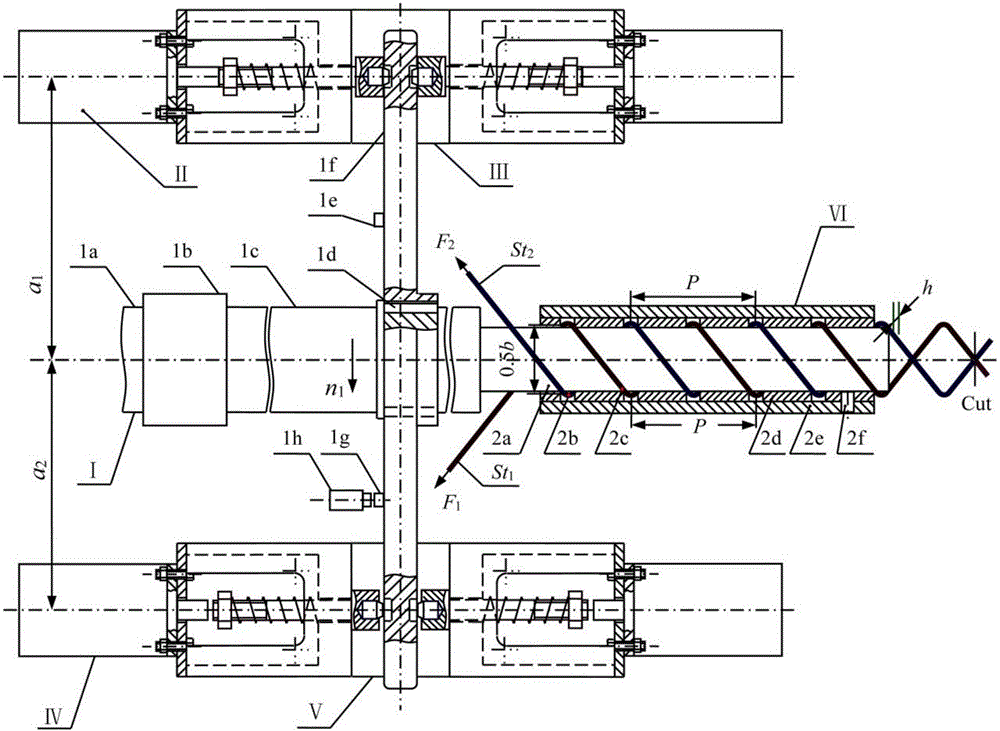
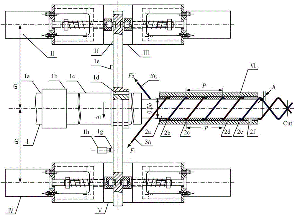
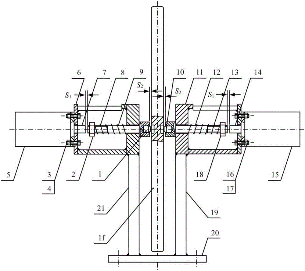
[0059] As shown in the picture figure 1 , figure 2 The double-position positioning device for the main shaft of a rhombic metal mesh knitting machine is shown, which includes a main shaft sensor system I, a main shaft upper positioning electromagnet push rod system II, a main shaft upper positioning electromagnet push rod system bracket III; a main shaft lower positioning electromagnet push rod system Rod system IV, spindle lower positioning electromagnet push rod system support V, forming structure VI of two inter-winding flat spiral steel wires, spindle input end 1a rotates continuously, when electromagnetic clutch 1b is energized, spindle output end 1c is driven, the spindle The output terminal 1c is connected with the key 1d to drive t...


PUM


Abstract

The invention discloses a main shaft double-position positioning device for a rhombic metal mesh knitting machine, belongs to the technical field of rhombic metal mesh knitting machines, and aims to solve the problems of large impact force, inaccurate positioning and difficulty in repair in the existing positioning way. The main shaft double-position positioning device comprises a main shaft sensor system, a main shaft upper-position positioning electromagnet push rod system, a main shaft upper-position positioning electromagnet push rod system bracket, a main shaft low-position positioning electromagnet push rod system, a main shaft lower-position positioning electromagnet push rod system bracket and a molded structure of two interwoven flat spiral steel wires. By adopting the main shaft double-position positioning device for the rhombic metal mesh knitting machine, the problem that impact and vibration are generated since an electromagnet push rod is directly pressed against the radial surface of a cam without any energy dissipation process, the problems that positioning is inaccurate and adjustment is difficult since an electromagnetic brake has an energy dissipation process as well as a positioning function, and the problems of gasification of oil, pitting corrosion of material surfaces and difficulty in replacing sealing parts in the positioning way of a crank slider mechanism are solved.

Description

technical field [0001] The invention belongs to the mechanical technical field of rhombic metal mesh weaving, and specifically relates to a double-position positioning device for a main shaft of a rhombic metal mesh weaving machine. Background technique [0002] Diamond-shaped metal mesh is widely used in fences in various occasions, slope protection of mines and roads, and coal mining false roof support. The rhombic metal mesh is manufactured by a special weaving machine, which is divided into a semi-automatic rhombic metal mesh weaving machine and a fully automatic rhombic metal mesh weaving machine. The process is the same. [0003] The forming mechanism of one flat spiral steel wire at a time is to install a forming guide plate coaxially on the main shaft of the rhombus metal mesh weaving machine. The length of the forming part of the forming guide plate is 2.5 times the pitch P of the flat spiral steel wire. The length of the non-forming part of the forming guide plate...

Claims


Application Information

Patent Timeline
IPC IPC(8): B21F27/02
CPCB21F27/02
Inventor 王洪欣李允旺
Owner CHINA UNIV OF MINING & TECH
Learn More