Pulsed electromagnetic shearing method and device

A pulsed electromagnetic and shearing device technology, used in shearing devices, shearing machine equipment, metal processing equipment, etc., can solve the problem of reducing the strength of mechanical support structures, and achieve the requirements for reducing strength, reducing demand, preventing curling effect

Active Publication Date: 2016-07-13
HUAZHONG UNIV OF SCI & TECH
View PDF7 Cites 3 Cited by
  • Summary
  • Abstract
  • Description
  • Claims
  • Application Information

AI Technical Summary

Problems solved by technology

[0009] Aiming at the limitations of the existing electromagnetic shearing method, the present invention proposes a pulsed electromagnetic shearing method and device, which can effectively prevent curling, burrs and wrinkles from occurring after the workpiece is sheared, and can reduce the impact on the mechanical support structure. The demand for strength, especially for the shearing of large thickness metal workpieces

Method used


Image

  • Pulsed electromagnetic shearing method and device
  • Pulsed electromagnetic shearing method and device
  • Pulsed electromagnetic shearing method and device

Examples


no. 1 example

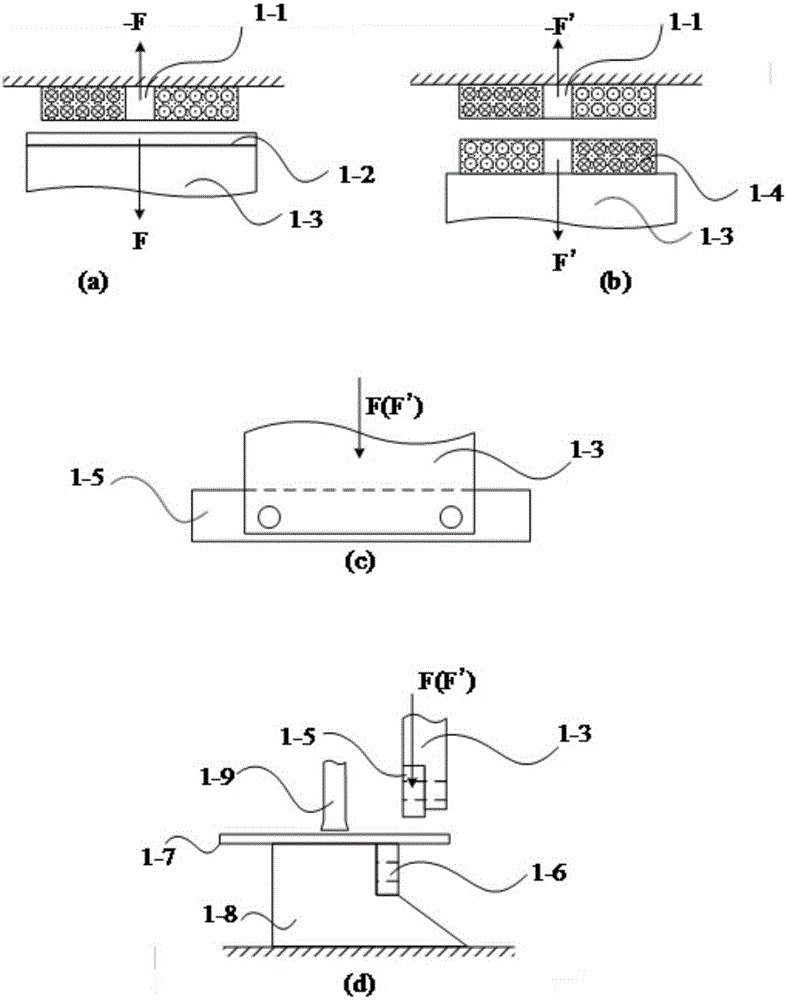
[0029] The generation of electromagnetic driving force, the mechanical transmission of electromagnetic force and the shearing process in the pulse electromagnetic shearing method of the present invention are as follows: figure 1 shown, where figure 1 (a) and figure 1 (b) illustrates two ways of generating pulsed electromagnetic force.

[0030] figure 1 The pulse magnetic force generating mechanism shown in (a) includes a pulse power supply, a pulse coil 1-1 and a driving board 1-2. Fix the pulse coil 1-1, discharge the pulse coil 1-1 through the pulse power supply, the pulse coil 1-1 generates a pulse magnetic field, and generates an induced eddy current on the drive plate 1-2, and the pulse magnetic field and the induced eddy current interact to generate a pulse electromagnetic force F, pushing the drive plate 1-2 to drive the mechanical transmission structure 1-3 to move.

[0031] figure 1 The pulsed magnetic force generating mechanism shown in (b) comprises a pulsed po...

no. 2 example

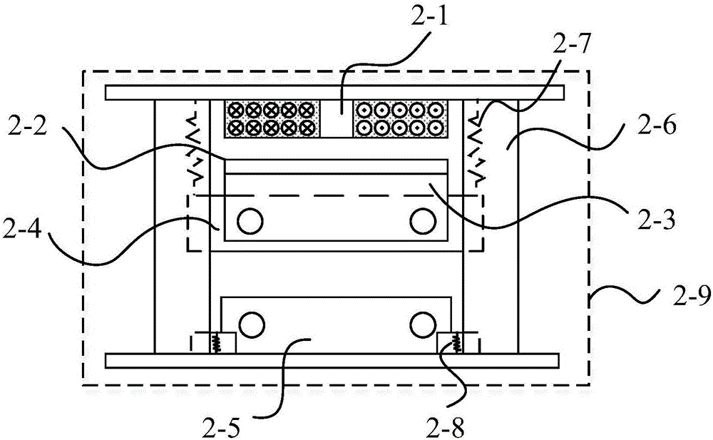
[0035] figure 2 It is a structural schematic diagram of a gantry type electromagnetic shearing machine, and its main components include: pulse coil 2-1, drive plate 2-2, mechanical transmission structure 2-3, upper blade 2-4, lower blade 2-5, base, The initial position fixing structure 2-7, the blade drop buffering structure 2-8, and the external support frame 2-9. The mechanical transmission structure includes a drive plate-upper blade connecting device 2-3 and a sliding guide rail 2-6. The driving board 2-2 is connected to the upper blade 2-4 through the connecting device 2-3, and the upper blade 2-4 is parallel to the lower blade 2-5. Wherein, the base is used to support the lower blade and the longitudinal sliding guide rail; the longitudinal sliding guide rail 2-6 is installed on the base, and the effect is to make the upper blade 2-4 slide smoothly in the direction of the guide rail. In order to make the most use of the pulsed electromagnetic force, before the shearin...

no. 3 example

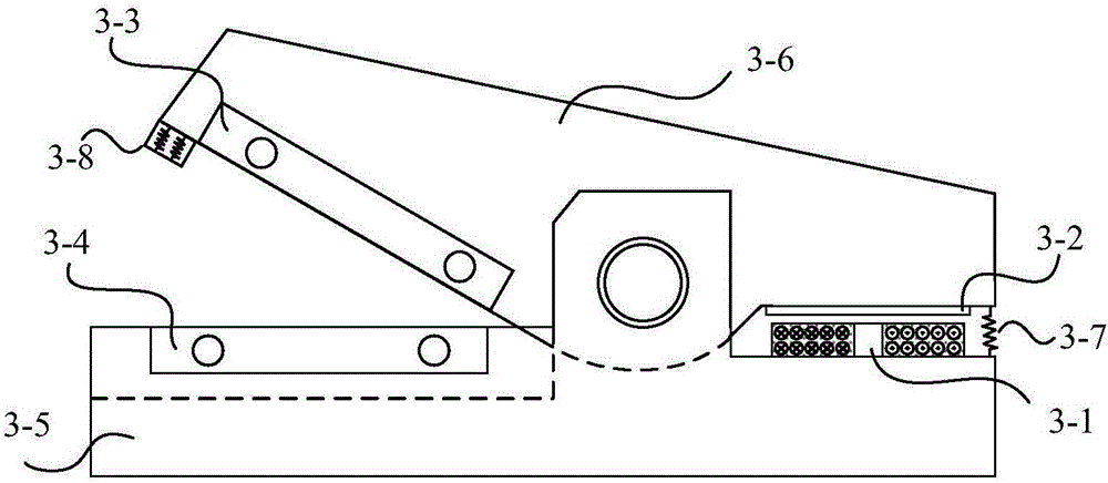
[0037] image 3 It is a structural schematic diagram of a crocodile-type electromagnetic shearing machine, and its main components include: a pulse coil 3-1, a drive plate 3-2, an upper blade 3-3, a lower blade 3-4, a base 3-5, and an upper knife arm ( Mechanical transmission structure) 3-6, initial position fixed structure 3-7, blade falling buffer structure 3-8. The drive plate 3-2 is connected to the upper blade 3-3 through the upper knife arm 3-6, and the upper blade and the lower blade form a V shape. Because the space density of the pulsed electromagnetic force is large, but the range of action space is small, so in this structure, the pulsed electromagnetic force acts on the drive plate 3-2 to make the force arm of the upper knife arm rotate counterclockwise, which makes the upper arm rotate counterclockwise than the shear resistance. The force arm of the clockwise rotation of the knife arm is small. The initial position fixing structure 3-7 is a kind of spring buckle...


PUM


Abstract

The invention discloses a pulsed electromagnetic shearing method and device.The method comprises the steps that a metal workpiece is placed between an upper blade and a lower blade, pulsed electromagnetic force is taken as driving force to drive the upper blade to move towards the lower blade, and the upper blade and the lower blade cooperate with each other to complete metal workpiece shearing.The device comprises the upper blade, the lower blade and a pulsed magnetic force generating mechanism, the lower blade is used for containing the metal workpiece, the pulsed magnetic force generating mechanism is used for generating the pulsed electromagnetic force, the pulsed electromagnetic force is taken as the driving force to drive the upper blade to move towards the lower blade, and the upper blade and the lower blade cooperate with each other to complete metal workpiece shearing.According to the pulsed electromagnetic shearing method and device, the electromagnetic cutting application field is expanded, the phenomenon that the defects such as turned edges, deckle edges and wrinkles are generated after workpiece shearing is completed is effectively prevented, and the requirement for the mechanical support structure strength can be effectively lowered.

Description

technical field [0001] The invention relates to the technical field of shearing, in particular to a pulse electromagnetic shearing method and device. Background technique [0002] Shearing machines are widely used in traditional metal cutting, plastic cutting and other fields. During the shearing process, the shearing machine needs to generate a huge driving force to push the blade to cut the workpiece. In this way, the maximum value of the driving force is also called the maximum shearing force, which is an important index to measure the shearing capacity of a shearing machine. At the same time, the mechanical structure of a shearing machine is also determined according to the maximum shearing force it can generate Optimized design. [0003] Most of the shearing driving force of the existing shearing machine is firstly generated by an electric motor or manpower, etc., and then transmitted through a mechanical transmission device such as a hydraulic device, a gear, a belt ...

Claims


Application Information

Patent Timeline
Patent Type & Authority Applications(China)
IPC IPC(8): B23D15/12
CPCB23D15/12
Inventor 李亮黄玉杰曹全梁李鑫周中玉赖智鹏
Owner HUAZHONG UNIV OF SCI & TECH
Why Eureka
Try Eureka