Resonant High Current Density Transformer

A high current density, resonant technology, used in transformers, transformer/inductor cores, transformer/inductor components, etc., can solve problems such as increased manpower and man-hours, difficult leakage inductance control, and difficulty in removing enameled packages.

Active Publication Date: 2018-01-09
MEANWELL GUANGZHOU ELECTRONICS
View PDF13 Cites 0 Cited by
  • Summary
  • Abstract
  • Description
  • Claims
  • Application Information

AI Technical Summary

Problems solved by technology

[0007] 1. Since the primary and secondary sides of common resonant transformers are wound with traditional wires (enameled wires), when outputting large currents, the secondary side winding structure of multi-strand wires is used to improve the current tolerance, but The winding structure wound with multi-strand wires (enameled wires) is not only difficult to remove the enamelled due to the excessive number of strands, but also has difficulties in outlet or connection, and there will be gaps between the wires (enameled wires), resulting in winding Even the size of the transformer cannot be reduced
[0008] 2. In the structure of common resonant transformers, the primary winding and the secondary winding are usually wound on different positions on a single wire frame (winding base). It consumes quite a lot of manpower, thus resulting in an increase in manpower and working hours
[0009] 3. In the structure of traditional resonant transformers, metal sheets are also used to replace the secondary side windings. However, if the primary and secondary side windings are arranged on the same wire frame, it is easy to cause disadvantages such as insufficient safety distance and difficult adjustment of leakage inductance. As a result, it is necessary to add an additional inductance to act as a resonant inductor; and if the primary and secondary side windings are wound on the second wire frame, it must be considered that the distance between the two wire frames is not easy to fix, resulting in characteristics such as leakage inductance that are difficult to control.

Method used


Image

  • Resonant High Current Density Transformer
  • Resonant High Current Density Transformer
  • Resonant High Current Density Transformer

Examples


Embodiment Construction

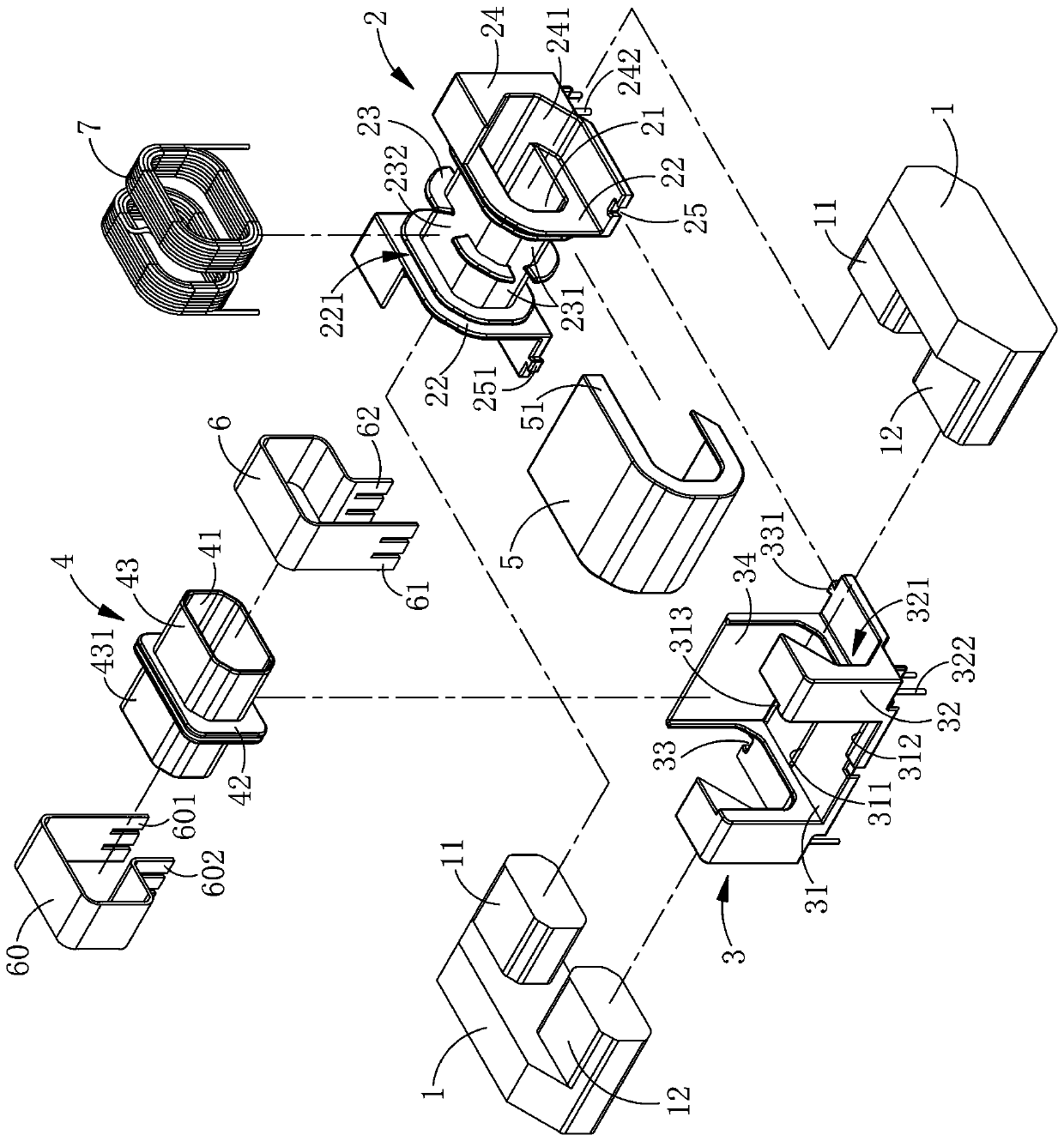
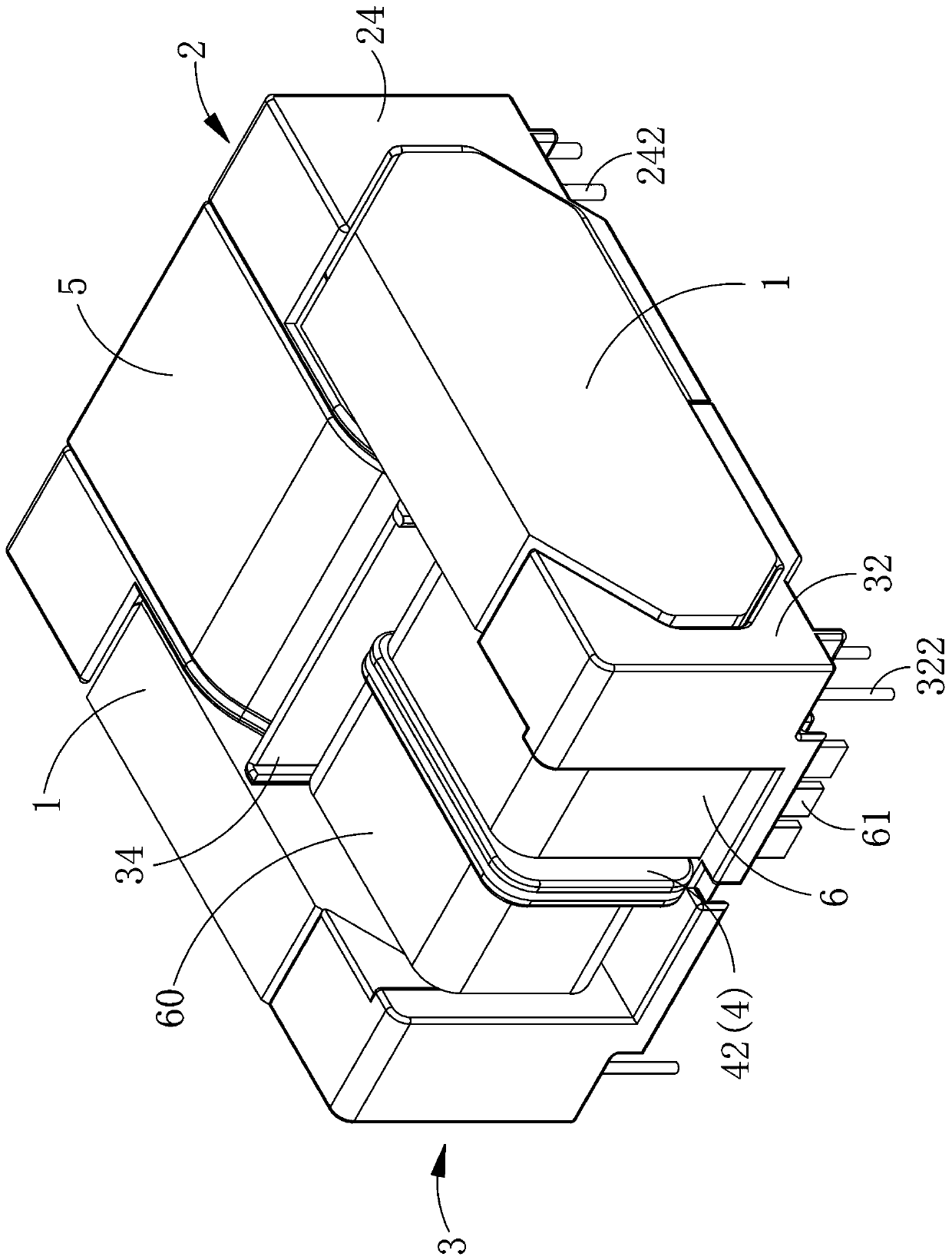
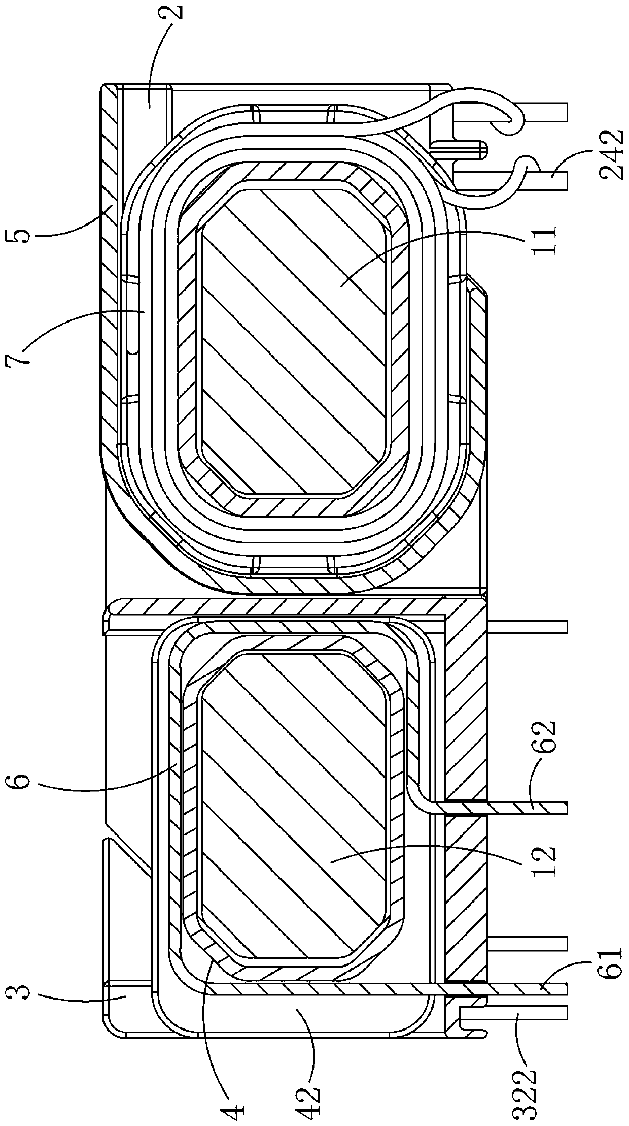
[0056] See Figure 1 to Figure 3 As shown, it can be seen that the structure of the present invention mainly includes: iron core 1, first bobbin 2, bobbin seat 3, second bobbin 4, separating cover 5, metal sheet 6, and primary winding 7; wherein The iron core 1 is provided with first and second side posts 11 and 12 protruding in the same direction on the two sides. When the two iron cores 1 face each other, the two first side posts 11 abut against each other, and the two second side posts 12 mutually Leaning against, can form a magnetic circuit.

[0057] The first bobbin 2 is provided with a first through hole 21 penetrating therethrough. The first through hole 21 is sleeved on the outer periphery of the first side column 11 on the same side of the two iron cores 1 and is located on the outer periphery of the two ends of the first through hole 21 A side plate 22 is provided on each side, a spacer 23 is provided between the two side plates 22, two wire grooves 231 are formed on t...


PUM


Abstract

According to a resonant type high-current-density transformer, two iron cores abut against each other through first side columns and second side columns preset on two sides, the first side columns on the same sides of the two iron cores are sleeved together through a first wire rack, the two ends of the first wire rack are each provided with a side plate, the space between the two side plates is partitioned by a partition piece to form two wire grooves, at least one wire is wound in each wire groove to form a primary side winding, the second side columns on the same sides of the two iron cores are sleeved together through a second wire rack, the peripheral side of the second wire rack is partitioned by a partition piece to form two winding areas, two metal sheets wrap the winding areas respectively to form a secondary winding, a wire rack base is arranged on the outer side of the second wire rack, a partition plate for separating the first wire rack and the second wire rack is arranged on one side of the wire rack base, an insulating partition cover is arranged on the side, close to the wire rack base, of the first wire rack, and the upper side and the lower side of the first wire rack are covered by two ends of the partition cover. The size of the transformer can be reduced, the high power density characteristic is achieved, the distance between the two wire racks is effectively fixed, and the leakage inductance and other characteristics of the transformer are controlled.

Description

Technical field [0001] The invention relates to a resonance type high current density transformer, in particular to a resonance type transformer that can reduce the volume, increase the power density, and is easy to automatically process and produce. Background technique [0002] In the power supply system of electronic products such as LCD TVs, the transformers are mostly based on transformers with leakage inductance (for example: resonant transformer LLC transformer), which can reduce switching loss and reduce noise. [0003] For example, Taiwan Patent Publication No. M333646 "Leakage Inductance Resonant Transformer Structure Improvement" new patent case: "The structure mainly includes: an outer wire frame with a first through hole, and the outer wire frame with a first recessed hole; An inner wire rack, the inner wire rack is sleeved in the first through hole of the outer wire rack, the inner wire rack is provided with a second through hole, and the inner wire rack is provided w...

Claims


Application Information

Patent Timeline
Patent Type & Authority Patents(China)
IPC IPC(8): H01F27/24H01F27/30H01F27/28H01F27/32H01F38/02
CPCH01F27/24H01F27/2847H01F27/306H01F27/325H01F38/02
Inventor 彭希和
Owner MEANWELL GUANGZHOU ELECTRONICS
Why Eureka
Try Eureka