
Automatic racking system for capacitors

An automatic mounting and capacitor technology, applied in the direction of capacitors, capacitor manufacturing, circuits, etc., can solve the problems of large operation time and small size of capacitors, and achieve the effect of saving time and improving production efficiency.

Inactive Publication Date: 2016-07-13
ANHUI PUHE ELECTRONICS
View PDF4 Cites 1 Cited by
  • Summary
  • Abstract
  • Description
  • Claims
  • Application Information

AI Technical Summary

Problems solved by technology

[0004] Capacitors need to be charged during the production process. In the charging process, in order to improve work efficiency, the capacitors that need to be charged are often placed on the charging rack to achieve the purpose of charging a large number of capacitors at one time. However, due to the small size of the capacitor , so it takes a lot of manipulation time to install the capacitor on the charging rack

Method used


Image

  • Automatic racking system for capacitors
  • Automatic racking system for capacitors
  • Automatic racking system for capacitors

Examples


Embodiment Construction

[0029] Below, the technical solution of the present invention will be described in detail through specific examples.

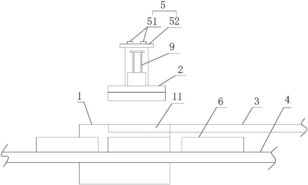
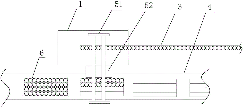
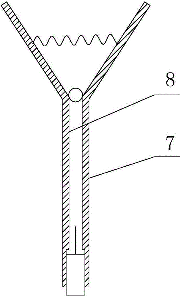
[0030] Such as Figure 1-3 as shown, figure 1 It is a structural schematic diagram of a capacitor automatic mounting system proposed by the present invention; figure 2 A top view of a capacitor automatic mounting system proposed by the present invention; image 3 It is a structural schematic diagram of the clamping head in an automatic capacitor racking system proposed by the present invention.

[0031] refer to image 3 , a capacitor automatic mounting system proposed by the embodiment of the present invention, including: a workbench 1, a clamping mechanism 2, a first transmission mechanism 3, a second transmission mechanism 4, a steering mechanism 5 and a driving mechanism, wherein:

[0032] The workbench 1 is arranged horizontally, and the workbench 1 is provided with a horizontally arranged bar-shaped groove 11, and one end of the bar-shaped groove 11...


PUM


Abstract

The invention discloses an automatic racking system for capacitors. The automatic racking system includes a workbench, a clamping mechanism, a first delivery mechanism, a second delivery mechanism, a steering mechanism an a driving mechanism, a strip-shaped groove is arranged on the workbench, and one end of the strip-shaped groove is provided with a feeding port; the first delivery mechanism is connected with the feeding port; the second delivery mechanism is parallel to the strip-shaped groove; the steering mechanism includes a guiding track, a sliding table and a first power unit, wherein the guiding track is horizontally arranged above the workbench and extends from the workbench towards the direction of the second delivery mechanism to above the second delivery mechanism; the sliding table is driven by the first power unit to move back and forth on the guiding track; the clamping mechanism is mounted on the sliding table and used for clamping capacitors in the strip-shaped groove; and the driving mechanism is used for driving the clamping mechanism to perform vertical lifting. The automatic racking system for capacitors realizes the purpose of automation of loading the capacitors on a charging rack, and avoids a process of manually installing a large number of capacitors on the charging rack, thereby saving a large amount of time, and improving production efficiency.

Description

technical field [0001] The invention relates to the technical field of capacitor processing, in particular to an automatic mounting system for capacitors. Background technique [0002] Capacitor is a device that holds charge. Capacitor is one of the electronic components widely used in electronic equipment. It is widely used in DC blocking, coupling, bypass, filtering, tuning loop, energy conversion, control and other aspects in the circuit. [0003] With the rapid development of electronic information technology, the upgrading speed of digital electronic products is getting faster and faster. The production and sales of consumer electronic products, mainly flat-panel TVs (LCD and PDP), notebook computers, digital cameras and other products, continue to grow. Capacitor industry growth. [0004] Capacitors need to be charged during the production process. In the charging process, in order to improve work efficiency, the capacitors that need to be charged are often placed on ...

Claims


Application Information

Patent Timeline
IPC IPC(8): H01G13/00
CPCH01G13/00
Inventor 刘劲松
Owner ANHUI PUHE ELECTRONICS
Learn More