Method and device for improving repetition frequency of laser

A repetition frequency and laser technology, applied in the laser field, can solve the problems of increasing the difficulty of mode locking, weak nonlinear effect, and increasing the difficulty of the process, and achieve the effect of reducing the difficulty of the assembly process, increasing the repetition frequency, and reducing the difficulty of mode locking

Inactive Publication Date: 2016-07-13
青岛自贸激光科技有限公司
View PDF6 Cites 7 Cited by
  • Summary
  • Abstract
  • Description
  • Claims
  • Application Information

AI Technical Summary

Problems solved by technology

The repetition frequency of the fiber laser is inversely proportional to the cavity length of the resonant cavity. There are three difficulties in increasing the repetition rate: 1. Integrating and assembling devices in a shorter cavity length increases the process difficulty; 2. In a shorter cavity length High-precision control of dispersion within the cavity length increases the difficulty of the process; 3. In the case of high repetition frequency, the single pulse energy is low and the nonlinear effect is weak, which increases the difficulty of mode-locking

Method used


Image

  • Method and device for improving repetition frequency of laser
  • Method and device for improving repetition frequency of laser
  • Method and device for improving repetition frequency of laser

Examples


Embodiment 1

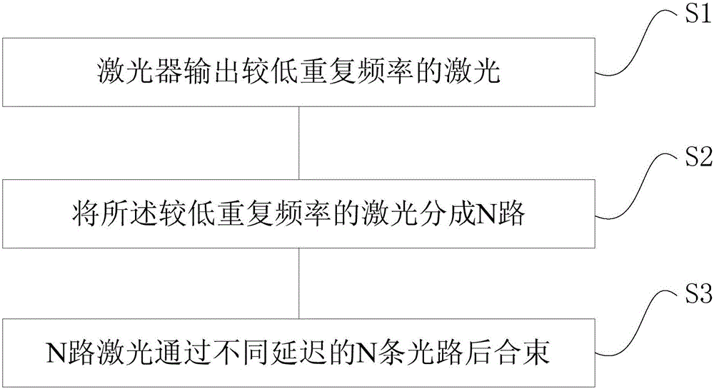
[0025] figure 1 A method of increasing the repetition rate of a laser is shown, comprising the steps of:

[0026] A method for increasing the repetition rate of a laser, comprising the steps of:

[0027] S1. The laser outputs laser with a lower repetition rate;

[0028] S2. Divide the laser light with a lower repetition rate into N paths;

[0029] S3. N laser beams are combined after passing through N optical paths with different delays.

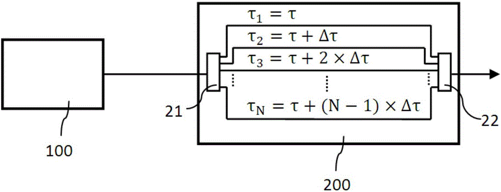
[0030] As preferably, in the step S3, the delays of the N optical paths are respectively τ 1 , τ 2 , τ 3 ...τ N , the delay difference between two adjacent optical paths

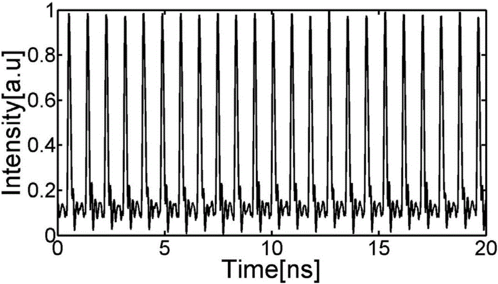
[0031] Preferably, in the step S1, the lower repetition frequency output by the laser is RF, and in the step S3, the laser repetition frequency after beam combining is equal to N×RF.

[0032] Preferably, the color difference between the N optical paths is less than 0.0003 ps / nm, so that the output laser pulse width can be restored to the input laser pulse width; ...

Embodiment 2

[0034] Figure 2 to Figure 4 A device for increasing the laser repetition rate is provided, including a laser 100 for outputting laser light, a TDM module 200 for increasing the laser repetition rate, and the TDM module 200 is used to divide the laser light into N paths, and after passing through N optical paths with different delays Be bundled.

[0035] In this embodiment, 100 uses a femtosecond fiber laser with a repetition rate of 72 MHz, a wavelength of 1550 nm, and a pulse width of 120 fs.

[0036] Preferably, the TDM module 200 includes a first optical splitter 21 and a second optical splitter 22, the first optical splitter 21 is used to divide the laser into N paths, and the second optical splitter The splitter 22 is used to combine N paths of light. In this embodiment, both the first optical splitter 21 and the second optical splitter 22 are 1×16 optical splitters.

[0037] Preferably, the laser light is divided into N paths and combined after passing through N light...


PUM


Abstract

The invention relates to a method and device for improving repetition frequency of a laser. The method includes the following steps: S1. the laser outputs laser of relatively low repetition frequency, and the repetition frequency of the laser output by the laser is RF; S2. the laser of the relatively low repetition frequency is divided into N paths; and S3. the N paths of laser passes through N optical paths with different delays and are combined. The repetition frequency of the laser after beam combination is equal to N*RF, and generally N>10 can be realized very easily. According to the method provided by the invention, the repetition frequency of the laser is improved outside a resonant cavity, thereby avoiding the repetition frequency from being limited by the cavity length of the resonant cavity. The repetition frequency of an ultrafast fiber laser in the market is generally 100MHz, and through the method, the repetition frequency can be increased to above GHz very easily.

Description

technical field [0001] The invention relates to the technical field of lasers, and more specifically relates to a method and a device for increasing the repetition rate of a laser. Background technique [0002] High repetition rate ultrafast fiber lasers have very important applications in high-speed optical sampling, precise ranging, optical frequency combs, optical storage, biomedicine and other fields. Ultrafast fiber lasers generally adopt passive mode locking. The resonator contains devices such as wavelength division multiplexers, optical isolators, and optical beam splitters. Each device has a certain package length, and it must be reserved for fiber-optic devices. A certain length of pigtail is used for fusion splicing, and a certain length of gain fiber is required in the cavity to provide sufficient gain. The repetition frequency of the fiber laser is inversely proportional to the cavity length of the resonant cavity. There are three difficulties in increasing the...

Claims


Application Information

Patent Timeline
Patent Type & Authority Applications(China)
IPC IPC(8): H01S3/10H01S3/067
CPCH01S3/10046H01S3/06708
Inventor 曹祥东罗文清
Owner 青岛自贸激光科技有限公司
Why Eureka
Try Eureka