Automatic voltage regulator with wide input voltage range

An automatic voltage regulator and voltage range technology, applied in the direction of output power conversion devices, electrical components, etc., can solve the problems of AVR not working normally, achieve the effect of increasing output voltage, reducing power loss, and saving energy

Active Publication Date: 2016-07-13
EATON MFG LP GLASGOW SUCCURSALE DE MOR
View PDF5 Cites 2 Cited by
  • Summary
  • Abstract
  • Description
  • Claims
  • Application Information

AI Technical Summary

Problems solved by technology

However, the starting voltage of the transfer switch usually needs to be higher than 9V, which requires the line voltage to be at least 140V. When the line voltage is lower than 140V, the AVR cannot work normally.

Method used


Image

  • Automatic voltage regulator with wide input voltage range
  • Automatic voltage regulator with wide input voltage range
  • Automatic voltage regulator with wide input voltage range

Examples


no. 1 example

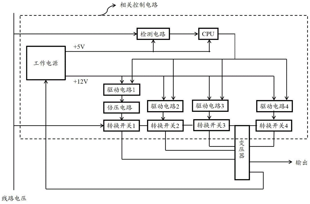
[0041] figure 2 It shows the structural block diagram of the AVR of the first embodiment of the present invention, the input end of the working power supply is electrically connected with an output tap of the transformer, and the line voltage is transmitted to the working power supply after being transformed by the transformer, and respectively supplied to the detection circuit, the CPU and the first The drive circuits of the first to fourth transfer switches are powered. Typical detection circuits and CPU require +5V start-up voltage, while the transfer switches require +12V start-up voltage. The detection circuit transmits the detected line voltage signal to the CPU, and the CPU further controls the start of each transfer switch. A voltage doubler circuit is also electrically connected between the first transfer switch and its drive circuit, which is used to increase the output voltage of the drive circuit of the first transfer switch to the starting voltage of the first tr...

no. 2 example

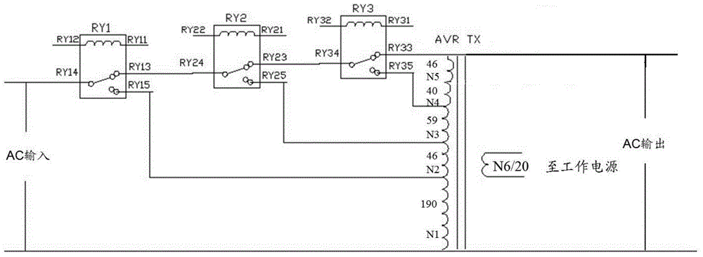
[0048] Figure 5 A schematic circuit diagram of another variant of the AVR of the present invention is shown. The difference from the structure of the AVR in the first embodiment is that in this embodiment, the normally closed end RY13 of the first transfer switch RY1 is connected to the common end RY34 of the third transfer switch RY3, and the normally open end of the first transfer switch RY1 RY15 is connected to the common end RY24 of the second transfer switch RY2, and the normally closed end RY23 and the normally open end RY25 of the second transfer switch RY2 are respectively directly connected to different input taps of the autotransformer AVRTX, which is equivalent to the connection between the second transfer switch RY2 and the second transfer switch RY2. Three transfer switches RY3 are connected in "parallel" to autotransformer AVRTX. The current flow direction of the AVR of this embodiment in different working modes is given below:

[0049] 1. Normal mode: input→c...

no. 3 example

[0067] Figure 6 and Figure 7 respectively image 3 and Figure 5 In the circuit schematic diagram of the modification of the AVR shown, a transfer switch RY5 is added behind the fourth transfer switch RY4 as an output control switch. When it is necessary to output voltage to the load device, start the transfer switch RY5.


PUM


Abstract

The invention aims to provide an automatic voltage regulator with a wide input voltage range. The automatic voltage regulator comprises a transformer with multiple groups of taps, a detection circuit, a CPU and a working power supply and also comprises a first conversion switch, a second conversion switch, and a third conversion switch which are electrically connected to different input taps of the transformer. The first conversion switch, the second conversion switch and the third conversion switch are mutually connected electrically and have the respective driving circuit, wherein the first conversion switch also has a voltage doubler circuit, the input end of the voltage doubler circuit is connected to the working power supply and the output end of the driving circuit of the first conversion switch, the output end of the voltage doubler circuit is connected to starting power supply end of the first conversion switch, and the voltage doubler circuit is used for raising the output voltage of the driving circuit of the first conversion switch to the starting voltage of the first conversion switch. Thus for power transmission and distribution line voltage with a wide voltage fluctuation range, the automatic voltage regulator can work normally.

Description

technical field [0001] The invention belongs to the field of automatic voltage regulators, in particular to an automatic voltage regulator with a wide input voltage range. Background technique [0002] A traditional Automatic Voltage Regulator (AVR) consists of a transformer, related control circuits and main protection devices. The related control circuit includes: working power supply, CPU, detection circuit, transfer switch and transfer switch driving circuit. [0003] In use, the power transmission and distribution lines are connected to the equipment through the AVR. There are many factors that cause voltage fluctuations in power transmission and distribution lines. When the voltage is high or low, the AVR will automatically adjust to provide a stable output voltage. When the voltage is too high or too low, the AVR will cut off the output to protect the device. [0004] For example, when the voltage of the power transmission and distribution line (referred to as the ...

Claims


Application Information

Patent Timeline
IPC IPC(8): H02M1/36
Inventor 蔡火圆胡双平吴晓东
Owner EATON MFG LP GLASGOW SUCCURSALE DE MOR
Why Eureka
Try Eureka