Electromagnetic resonance circuit and electromagnetic heating device

A resonant circuit and electromagnetic resonance technology, which is applied in the field of electromagnetic heating devices and electromagnetic resonant circuits, can solve the problems of mutual interference between voltage connections, heating circuits that cannot be heated at the same time, and circuit stop oscillation, so as to avoid current stop oscillation and circuit control complexity , to avoid the effect of transistor breakdown

Active Publication Date: 2019-03-08
FOSHAN SHUNDE MIDEA ELECTRICAL HEATING APPLIANCES MFG CO LTD +1
View PDF6 Cites 0 Cited by
  • Summary
  • Abstract
  • Description
  • Claims
  • Application Information

AI Technical Summary

Problems solved by technology

[0002] At present, the electromagnetic heating products that use two independently working coil disks to heat different parts of the pot need to use two IGBTs (Insulated Gate Bipolar Transistor, insulated gate bipolar transistor) to control the two coil disks respectively. When using an IC (Integrated Circuit, integrated circuit) with a programmable pulse generator to control the IGBT, it will be affected by the IC (such as figure 1 Shown in 102) there is only one programmable pulse generator port (PPG port) limitation; meanwhile, the existing IC detects the synchronous signal port ( figure 1 There is only one pair of VA and VB shown in , so that the existing circuit can only time-multiplex the two IGBT drive loops and synchronous signal loops. This kind of circuit usually has the following problems:
[0003] 1) The two heating circuits cannot be heated at the same time;
[0004] 2) There is a problem of voltage connection and mutual interference in the multiplexed synchronous signal circuit, which affects the accuracy of the synchronous signal. In severe cases, it will cause IGBT breakdown or the circuit will stop oscillating without heating;
[0005] 3) Even if the electronic switch circuit 104 is used to realize the switching of the IGBT control, there will be problems of complicated circuit control and poor reliability

Method used


Image

  • Electromagnetic resonance circuit and electromagnetic heating device
  • Electromagnetic resonance circuit and electromagnetic heating device
  • Electromagnetic resonance circuit and electromagnetic heating device

Examples


Embodiment Construction

[0026] In order to understand the above-mentioned purpose, features and advantages of the present invention more clearly, the present invention will be further described in detail below in conjunction with the accompanying drawings and specific embodiments. It should be noted that, in the case of no conflict, the embodiments of the present application and the features in the embodiments can be combined with each other.

[0027] In the following description, many specific details are set forth in order to fully understand the present invention. However, the present invention can also be implemented in other ways different from those described here. Therefore, the protection scope of the present invention is not limited by the specific details disclosed below. EXAMPLE LIMITATIONS.

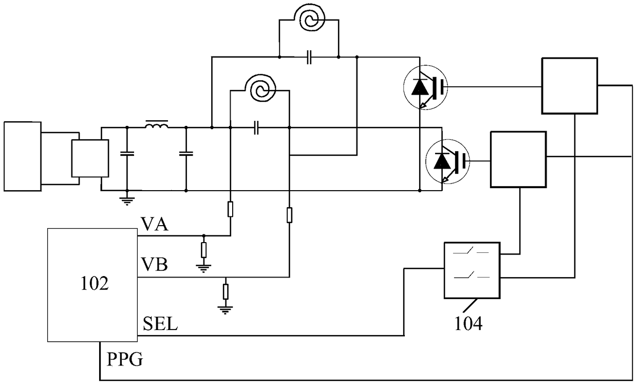
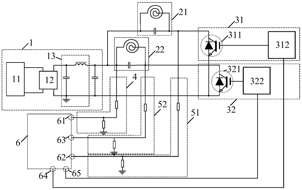
[0028] figure 2 A schematic structural diagram of an electromagnetic resonance circuit according to an embodiment of the present invention is shown.

[0029] Such as figure 2 As shown, the elect...


PUM


Abstract

The invention provides an electromagnetic resonant circuit and an electromagnetic heating device. The electromagnetic resonant circuit comprises a power supply module, a first resonance circuit, a second resonance circuit, a first transistor assembly, a second transistor assembly, a reference signal detection circuit, a resonant synchronous detection circuit and a control chip. The resonant synchronous detection circuit comprises a first synchronous detection circuit and a second synchronous detection circuit. The control chip comprises a reference signal input port connected with the second end of the reference signal detection circuit, a first synchronous signal input port connected with the second end of the first synchronous detection circuit, a second synchronous signal input port connected with the second end of the second synchronous detection circuit, a first drive signal output port connected with the input end of the first transistor assembly, and a second drive signal output port connected with the input end of the second transistor assembly. According to the technical scheme of the invention, two heating circuits are arranged to realize the heating effect at the same time. Meanwhile, the signal loops of the above two circuits are prevented from interring each other, so that the reliability of the system is improved.

Description

technical field [0001] The invention relates to the technical field of electromagnetic resonance, in particular to an electromagnetic resonance circuit and an electromagnetic heating device. Background technique [0002] At present, the electromagnetic heating products that use two independently working coil disks to heat different parts of the pot need to use two IGBTs (Insulated Gate Bipolar Transistor, insulated gate bipolar transistor) to control the two coil disks respectively. When using an IC (Integrated Circuit, integrated circuit) with a programmable pulse generator to control the IGBT, it will be affected by the IC (such as figure 1 Shown in 102) there is only one programmable pulse generator port (PPG port) limitation; meanwhile, the existing IC detects the synchronous signal port ( figure 1 There is only one pair of VA and VB shown in , so that the existing circuit can only time-multiplex the two IGBT drive loops and synchronous signal loops. This kind of circui...

Claims


Application Information

Patent Timeline
Patent Type & Authority Patents(China)
IPC IPC(8): H05B6/06
Inventor 黄庶锋房振李新峰卞在银黄开平李信合董凯何毅东王强徐双江雷俊
Owner FOSHAN SHUNDE MIDEA ELECTRICAL HEATING APPLIANCES MFG CO LTD
Why Eureka
Try Eureka