A hot rod saw

A technology of hot rods and cutting saws, which is applied in the direction of sawing machine devices, metal sawing equipment, metal processing equipment, etc., which can solve the problems of horizontal cutting aluminum rod costs, unrivaled sawing rods, and not easy to discharge, so as to save materials , High material utilization rate, the effect of saving raw material utilization rate

Active Publication Date: 2019-03-29
佛山市法比澳挤压机械科技有限公司
View PDF8 Cites 0 Cited by
  • Summary
  • Abstract
  • Description
  • Claims
  • Application Information

AI Technical Summary

Problems solved by technology

[0003] The traditional long rod length detection process is before the heating process. During the production process, it is often necessary to replace and exchange aluminum rods of different sizes or different alloy types due to different orders. The extra aluminum profiles will artificially remove the aluminum rods in the heating furnace. Go, this leads to the confusion of the parameters automatically set in advance by the PLC control system; and the traditional aluminum rod fixed-length and hot sawing equipment have the defects of unparalleled sawing function, resulting in waste of bar material, poor measurement accuracy, and poor system adaptability
Also, when the cutting saw cuts the aluminum rod, it cuts the aluminum rod horizontally. Figure 8 As shown, with this sawing method, the chips fall vertically, and the scattered chips fall on the machine not only for cleaning, but also for easy damage to the machine.
At the same time, cutting the aluminum rod horizontally costs and consumes electricity, and the cutting saw is also easy to damage; and it is easy to block and not easy to drain

Method used


Image

  • A hot rod saw
  • A hot rod saw
  • A hot rod saw

Examples


Embodiment Construction

[0022] Below in conjunction with accompanying drawing, invention is described in further detail.

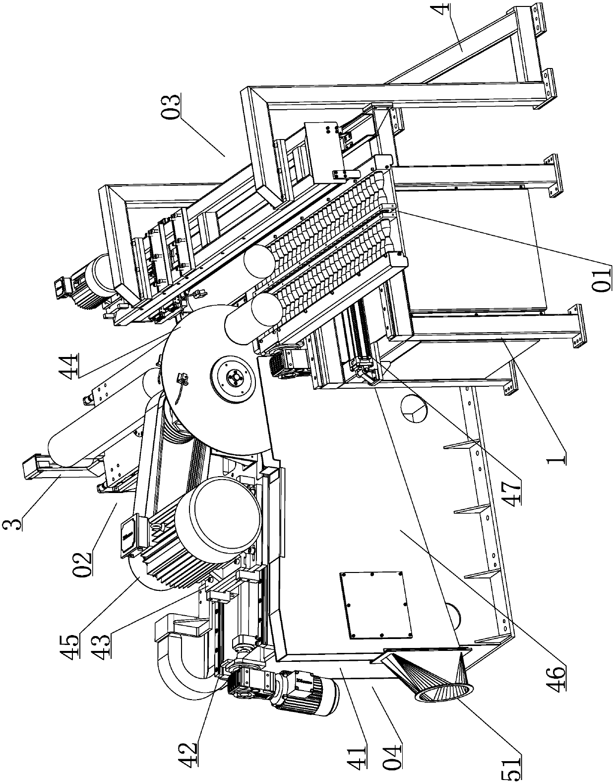
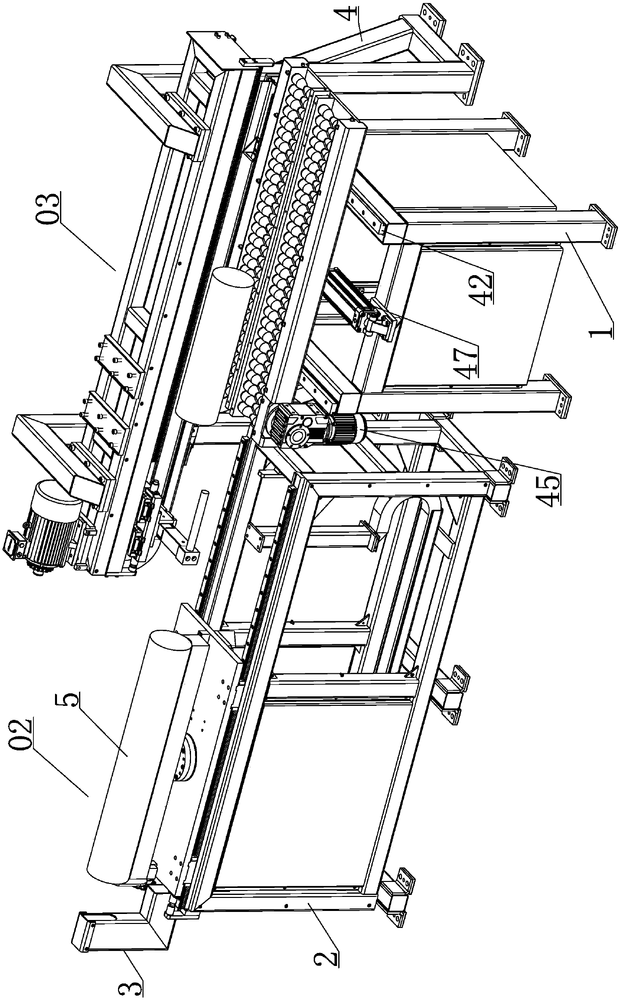
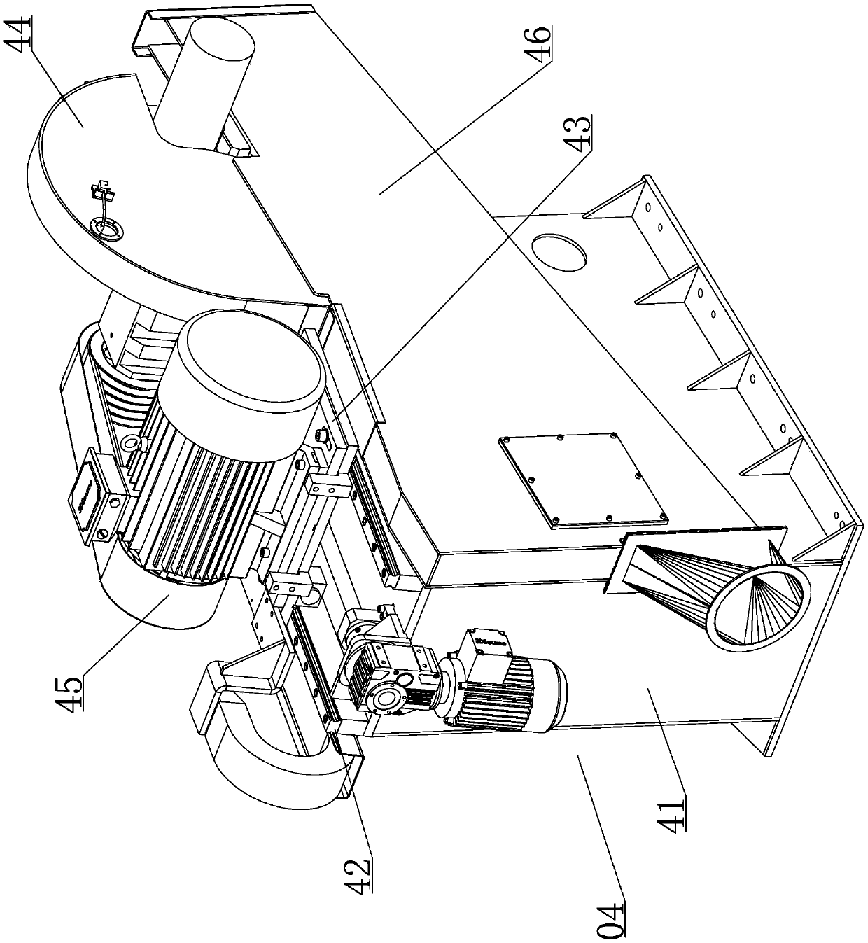
[0023] Such as Figure 1-7 and Figure 9 Shown, a kind of hot bar saw comprises a first support 1, a feed table 01 for conveying aluminum rods 5 is provided on the first support 1, a second support 2 is provided on one side of the first support 1, and a second support 2 is provided on the second support. The support 2 is provided with a rotating table 02 for rotating the aluminum rod 5, a laser measuring instrument 3 for measuring the length of the aluminum rod 5 is provided on the end of the second support 2, and a third support 4 is provided on one side of the first support 1. 1. On the third support 4, there is a transportation aid device 03 that cooperates with the feeding table 01 to transport the aluminum rod 5, and a sawing device 04 is provided between the first support 1 and the second support 2. The sawing device 04 comprises a support 41, on which the support 41 is p...


PUM


Abstract

The invention discloses a hot stick saw, wherein the hot stick saw comprises a first support frame, a material feeding table, a second support frame, a rotation table, a laser tester, a third support frame, a convey assistant device and a cutting saw device, wherein the third support frame is arranged at one side of the first support frame, the convey assistant device is arranged on the third support frame and used for conveying an aluminum stick cooperating with the material feeding table and the cutting saw device is arranged between the first support frame and the second support frame. The cutting saw device comprises a motor base, a first guiding rail, a guiding plate, a cutting saw body, a first motor and a cutting chip collecting groove, wherein the first guiding rail inclines to one side of the supporting frames; the guiding plate sliding obliquely is arranged on the first guiding rail; the cutting saw body is arranged on the guiding plate, the first motor in transmission with a cutting saw belt is arranged on the guiding board, and the cutting chip collecting groove with an opening larger than the diameter of the cutting saw body is formed in the motor base which is located on the bottom of the cutting saw body. The cutting saw body cuts the aluminum stick on the material feeding table obliquely downwards. The opening position of the cutting chip collecting groove corresponds to the direction that cutting chips are generated obliquely downwards after the cutting saw body cuts the aluminum stick obliquely downwards. The hot stick saw has the effects that power is saved, the structure is durable, materials are saved, machining is conducted automatically, labor cost is saved, and the working efficiency is improved.

Description

technical field [0001] The invention belongs to the field of aluminum rod processing, in particular to a hot rod saw. Background technique [0002] At present, when processing aluminum materials on the market, aluminum rods need to be cut to length and hot-sawed before being sent to an extrusion machine to be extruded into aluminum profiles. [0003] The traditional long rod length detection process is before the heating process. During the production process, it is often necessary to replace and exchange aluminum rods of different sizes or different alloy types due to different orders. The extra aluminum profiles will artificially remove the aluminum rods in the heating furnace. Go, this leads to the confusion of the parameters automatically set in advance by the PLC control system; and the traditional aluminum rod fixed-length and hot sawing equipment has the defects of unparalleled sawing function, resulting in waste of bar material, poor measurement accuracy, and poor sy...

Claims


Application Information

Patent Timeline
Patent Type & Authority Patents(China)
IPC IPC(8): B23D47/00B23D47/04
CPCB23D47/00B23D47/04
Inventor 傅昌明陈玉山邓孟齐文龙
Owner 佛山市法比澳挤压机械科技有限公司
Why Eureka
Try Eureka