
A welding trolley

A technology for welding trolleys and frames, which is applied in welding equipment, auxiliary welding equipment, welding/cutting auxiliary equipment, etc., and can solve problems such as accidental loss, slipping, and interference with the running speed of welding trolleys.

Active Publication Date: 2017-11-21
湖州佳灏信息技术有限公司
View PDF4 Cites 0 Cited by
  • Summary
  • Abstract
  • Description
  • Claims
  • Application Information

AI Technical Summary

Problems solved by technology

[0003] However, due to the existence of these slopes, it may interfere with the control of the running speed of the welding trolley
Moreover, when the slope is large, the accidental loss of power of the welding trolley may cause accidents such as slipping
When the slope is small, the acceleration due to the influence of gravity may also interfere with the speed of travel

Method used

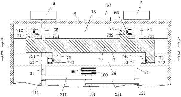
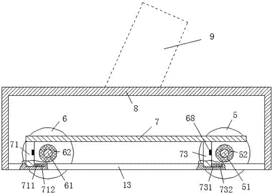
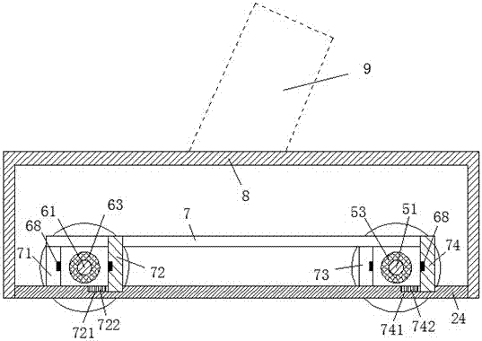

Image

  • A welding trolley
  • A welding trolley
  • A welding trolley

Examples


Embodiment Construction

[0010] Refer below Figure 1-3 Instead, examples of the present invention will be described.

[0011]The welding trolley according to the embodiment comprises a vehicle frame body 8 for carrying a welding torch 9, a front wheel axle 61 fixedly mounted with the front wheel 6 and rotatably connected with the vehicle frame body 8, and a rear wheel 5 fixedly mounted with the vehicle frame body 8. The frame body 8 is rotatably connected to the rear wheel shaft 51, and the front wheel shaft 61 is separately installed with a first one-way bearing 62 and a second one-way bearing 63 of the front shaft, which can rotate in opposite directions in the axial direction, The rear axle 51 is separately installed with the first one-way bearing 52 and the second one-way bearing 53 of the rear axle which can rotate in the opposite direction in the axial direction, and the front axle 61 is also provided with a front driving wheel. 111, the front driving wheel 111 is power connected with the driv...


PUM


Abstract

A welding trolley comprises a frame body (8) for bearing a welding gun (9), a front axle (61) fixedly provided with front wheels (6) and rotationally connected with the frame body (8), and a rear axle (51) fixedly provided with rear wheels (5) and rotationally connected with the frame body (8).A front axle first one-way bearing (62) and a front axle second one-way bearing (63) with opposite rotational directions are axially and separately installed on the front axle (61).A rear axle first one-way bearing (52) and a rear axle second one-way bearing (53) with opposite rotational directions are axially and separately installed on the rear axle (51).A front driving wheel (111) is further arranged on the front axle (61) and is in power connection with a driving wheel (101) driven by a motor (100) through a front transmission belt (211).A rear driving wheel (121) is further arranged on the rear axle (51).

Description

technical field [0001] The invention relates to the field of welding technology, in particular to a welding trolley. Background technique [0002] In the field of welding, especially in the continuous welding process, it is often necessary to use a welding trolley attached with a welding torch to continuously weld the weld seam. Due to the different shapes of the weld seam of the workpiece, the welding trolley may experience a horizontal route segment, an uphill route segment with a forward inclination angle or a downhill route segment with an inclination angle during operation. In each route segment, the welding carriage can perform forward and reverse travel directions. [0003] However, due to the existence of these slopes, it may interfere with the control of the running speed of the welding trolley. Moreover, when the slope is large, accidental loss of power of the welding trolley may cause accidents such as slipping. On smaller slopes, acceleration due to the influe...

Claims


Application Information

Patent Timeline
Patent Type & Authority Patents(China)
IPC IPC(8): B23K37/02
CPCB23K37/0294
Inventor 王磊
Owner 湖州佳灏信息技术有限公司
Learn More