Buffer aligning joint

A self-aligning and ball joint technology, which is used in drilling equipment, earth-moving drilling, drill pipes, etc., can solve the problems of inability to drill tools, lack of self-aligning function, affecting drilling construction, etc., and achieve the effect of improving construction efficiency.

Inactive Publication Date: 2016-07-20
SINOPEC SHENGLI PETROLEUM ENG CO LTD DRILLING TECH RES INST
View PDF12 Cites 0 Cited by
  • Summary
  • Abstract
  • Description
  • Claims
  • Application Information

AI Technical Summary

Problems solved by technology

[0002] At present, the output torque of the top drive in domestic drilling is transmitted to the downhole drill bit or other tools through the threaded drilling tool. The drilling tool directly connected with the thread is more rigid. When the drilling tool jumps, the impact force will directly act on the The power output end of the top drive, and when the output shaft of the top drive force has a large eccentricity relative to the wellhead, it is used for the rigid connection between the drilling tool and the top drive, which will affect the drilling construction, especially for casing drilling or rotary drilling. During the construction operation of the casing running with the circulating casing device, the threads of the butt casing are prone to thread cross-threading
The existing patent, US8684851's "Floating Sub Tool" ("FLOATINGSUBTOOL"), realizes the transmission of top drive torque and bears the axial force, and can buffer the axial impact force transmitted from the drilling tool to the top drive during the drilling process. However, it does not have the centering function, and it cannot solve the problem of large eccentricity of the top driving force output shaft relative to the wellhead.
Application No. CN201220563576.5 "Horizontal Well Flexible Nipple" and Application No. CN03235201.8 "A Toothed Universal Coupling" have realized the function of aligning the drilling tool, but they cannot buffer the drilling tool during the drilling process. Axial impact force generated, and CN03235201.8 "A Toothed Universal Coupling" cannot provide mud circulation channels for drilling tools

Method used


Image

  • Buffer aligning joint
  • Buffer aligning joint
  • Buffer aligning joint

Examples


Embodiment Construction

[0017] The present invention will be further described below in conjunction with the accompanying drawings.

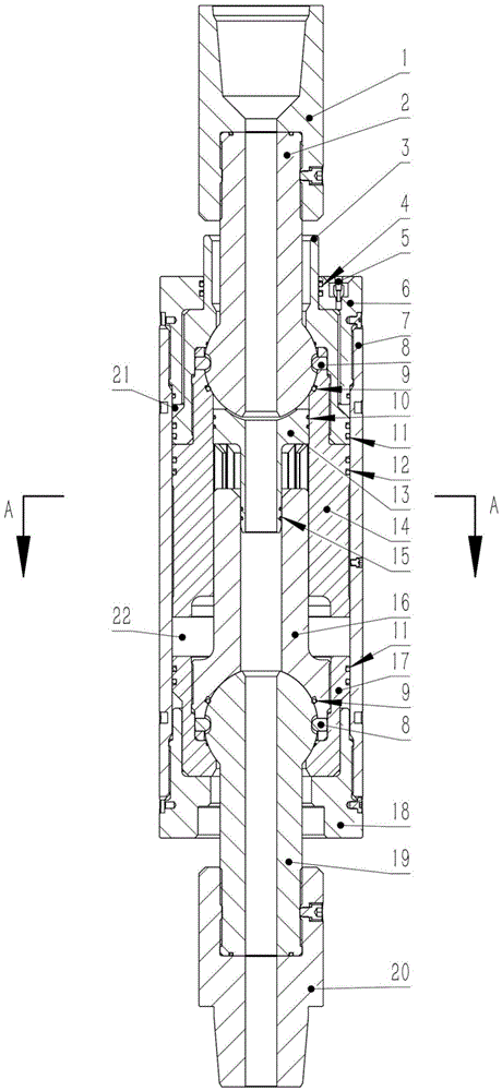
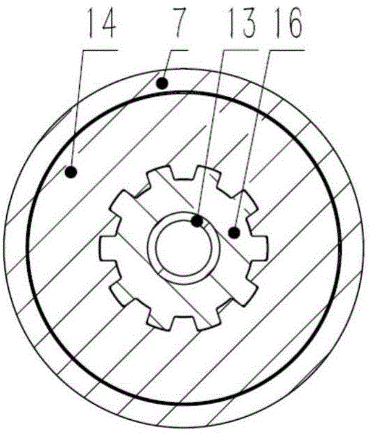
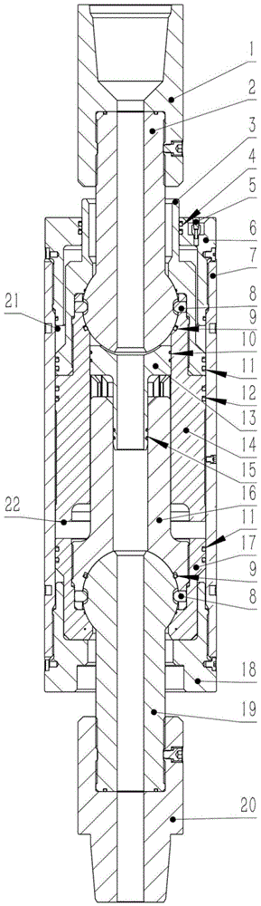
[0018] exist figure 1 As shown in , when in use, the output end of the top driving force is connected to the upper joint 1, and the lower end of the lower joint 20 is connected to the drilling tool. The upper joint 1 is connected with the upper ball joint 2, and the upper ball joint 2 is installed in the ball hole formed after the upper ball seat 3 and the inner spline 14 are threaded, and the ball pin 8 is installed in the outer circle of the inner spline 14 through the hole. In the blind hole of the spherical outer circle of the upper ball joint 2, the upper ball joint 2 and the inner spline 14 are hingedly fixed together. exist figure 2 As shown, the inner spline 14 and the outer spline 16 are plugged together and can move relative to each other in the axial direction within a certain distance. The lower ball joint 19 is installed in the ball hole formed after t...


PUM


Abstract

The invention relates to a buffer aligning joint in the field of oil gas exploration and development tools. The buffer aligning joint comprises an upper ball joint, an upper ball seat, an upper end cover, an outer cylinder, a ball pin, a jet pipe, an internal spline, an external spline, a lower ball seat, a lower end cover, a lower ball joint, a lower ball seat and the like. A ball head of the upper ball joint and a ball head of the lower ball joint are installed in a spherical cavity which is defined by the upper ball seat, the lower ball seat, the internal spline and the external spline. The external spline is inserted into a spline groove of the internal spline. A slurry circulating channel is formed by a central hole of the upper ball joint, a central hole of the jet pipe, a central hole of the external spline and a central hole of the lower ball joint. An upper gas chamber is formed by the upper end cover, an upper ball seat and the outer cylinder. A lower gas chamber is formed by the internal spline, the external spline, the outer cylinder and the lower ball seat. When the buffer aligning joint is used for well drilling, the torque can be transferred to a drilling tool, the axial force can be borne, the circulating channel is provided for slurry, the axial impact force is buffered, a top drive is protected, large misalignment which probably happens to a power output shaft of the top drive relative to the axis of a wellhead is compensated, construction is convenient, and the construction efficiency is improved.

Description

Technical field [0001] The invention relates to a buffer self-aligning joint in the field of oil and gas exploration and development tools, which is used for drilling rigs equipped with top drives, and can transmit torque to drilling tools and withstand axial forces during drilling, provide circulation channels for mud and buffer axial forces. impact force, and can also be used to complete downhole casing construction operations. Background technique [0002] At present, the output torque of the top drive in domestic drilling is transmitted to the downhole drill bit or other tools through the threaded drilling tool. The drilling tool directly connected with the thread is more rigid. When the drilling tool jumps, the impact force will directly act on the The power output end of the top drive, and when the output shaft of the top drive force has a large eccentricity relative to the wellhead, it is used for the rigid connection between the drilling tool and the top drive, which...

Claims


Application Information

Patent Timeline
Patent Type & Authority Applications(China)
IPC IPC(8): E21B17/02
Inventor 聂云飞吴仲华张俊杰赵宗峰宁仁磊王彬庒伟孙振刚左灵梁海明田宗正李明朝陈忠帅张锐
Owner SINOPEC SHENGLI PETROLEUM ENG CO LTD DRILLING TECH RES INST
Why Eureka
Try Eureka